What is a Trip Circuit Supervision Relay?
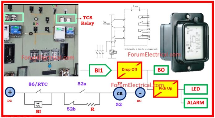
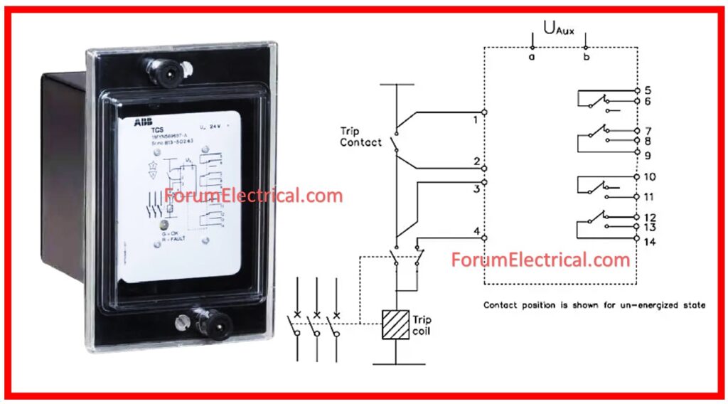
The TCS supervision relay is designed to continuously monitor the circuit breaker trip circuit and provide an alarm in the event of a loss of auxiliary supply, faults on the trip coil (or) its wires independently of the breaker position, faults on breaker auxiliary contacts, and faults in the supervision relay itself.
- What is a Trip Circuit Supervision Relay?
- How does Trip Circuit Supervision Relay Works?
- Pre-Close Trip Circuit Supervision
- Post-Close Trip Circuit Supervision
- How to implement the TCS using Numerical Relay?
- Supervision using single Binary Input (BI)
- TCS in Numerical Relay using Dual (or) Double Binary Input (BI)
- Testing Procedure of Trip Coil Supervision Relay
- Task
- Preconditions
- Precautions
- Scope
- Visual Inspection
- Testing the Trip Circuit Supervision (TCS) Relay
- Electrical Function Test
- Functional Check of Test Plug
- Secondary Injection Test
- Voltage Pick-up Verification Test
- Voltage Drop-Out Verification Test
- Function Check
- Documentation
How does Trip Circuit Supervision Relay Works?
Trip Circuit Supervision The circuit detects any malfunction in the trip coil of the breaker or the trip circuit.
When a fault is detected, the TCS Relay changes its contact condition and displays a window annunciation on the panel.
A fault in the circuit refers to any break (or) open circuit.
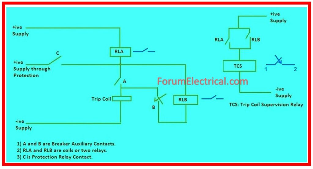
A breaker has two trip coils. If the relay generates a tripping command, both trip coils will energize. The circuit breaker mechanism opens when the trip coil is energized.
As a result, it is essential to monitor the trip coil’s condition because the breaker cannot open within the required time to remove the fault.
The Trip Circuit Supervision relay is provided to contact the condition of the trip coil.
As there are two trip coils, so there will be 2 Trip Circuit Supervision Relays, resulting in two distinct circuits.
This relay has 3 coils:
- RLA,
- RLB, and
- Main coil (TCS).
Subsequently, the breaker could be open (or) closed, consequently it’s required to monitor its health in both states.
Consequently, trip circuit supervision is separated into two parts:
- Pre-Close Supervision and
- Post-Close Supervision.
Contacts A & B are the breaker auxiliary contacts.
Keep in consideration that these contacts are linked to the breaker mechanism, therefore their status is determined by the position of the breaker. If the breaker is open, contact
A will be OPEN, while contact B will be CLOSE. Similarly, if the breaker is closed, contact B will be OPEN & contact A will be CLOSE.
We will now consider pre- and post-close supervision separately.
Pre-Close Trip Circuit Supervision
Pre-close indicates that the breaker is open. As a result, contact A’s status will be OPEN, whereas B’s will be CLOSE.
If you look closely at the circuit, you’ll note that current is flowing through both coils RLA and RLB. As coils RLA & RLB are activated, their contact will become close.
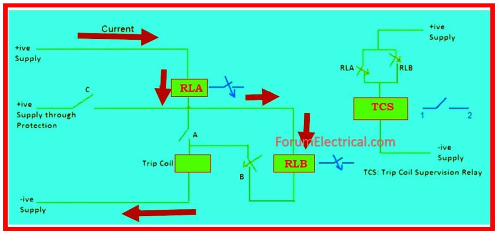
Subsequently inspect the TCS Relay circuit. Because RLA & RLB are similar, the DC supply should be further provided & the TCS relay should be turned on.
As a result, its output contacts 1 and 2 will be open, and no window will emerge. This indicates that trip circuit is operational.
Assume there is an open circuit; in this case, no current will pass through the coils RLA & RLB, thus relay TCS will not be activated.
As a result, output contact 1-2 will be closed during window annunciation. This indicates to the operator that either the DC supply has failed (or) there is a problem in the trip circuit.
Post-Close Trip Circuit Supervision
A post near indicates that the breaker is close. As a result, contact A’s status will be CLOSE, whereas B’s will be OPEN.
If you thoroughly analyze the circuit, you will see that current is flowing across both RLA coils.
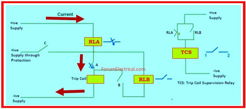
Now, thoroughly check the TCS Relay circuit. Because the RLA’s output contact is closed, the DC supply will be prolonged to the TCS relay, causing it to be powered.
As a result, its output contacts 1 and 2 will be open, and no window will emerge. This indicates that trip circuit is operational.
Assume there is an open circuit; in this scenario, no current can pass through the coils RLA, so relay TCS will not be activated. As a result, output contacts 1-2 will be near to the annunciate window.
This indicates to the operator that either the DC supply has failed (or) there is a problem in the trip circuit.
It should be noted that because the resistance of the relay coil is low, a large resistance should be connected in series to ensure that less current travels via the circuit to operate the breaker’s trip coil.
It should also be noted that, in the case of a protection trip, a separate positive DC voltage is applied to the circuit breaker’s trip coil, allowing full current to flow through the coil to operate the breaker.
How to implement the TCS using Numerical Relay?
With reference to and use the Relay’s Bi it is connected in series with CB Auxiliary contact & Trip coil to monitor CB condition.
This can be used to indicate the (TCH) – Trip Circuit Healthy illumination condition.
If the mapped Binary inputs are de-energized owing to a break (or) short circuit in trip circuit wire, the Binary output (BO) should be set to make an announcement or remote alert.
It can also be utilized for interlocking in the circuit breaker closing circuit.
Supervision using single Binary Input (BI)

The system mentioned before is used to supervise the trip coil with the CB open or closed condition. However, no pre-closing supervision is identified. Depending upon the trip contact and circuit breaker determine whether the (BI) binary inputs are activated or not.
In normal operation, the binary input activates when the trip contact is open and the trip circuit is complete. The monitoring circuit is made closed by either the 52a circuit breaker auxiliary contact (if closed) or the 52b circuit breaker auxiliary contact (via the bypass resistor).
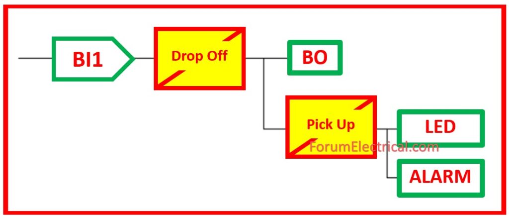
This is only after the 86 that the (master trip) trip contact is closed and hence the (BI) binary input is rendered inactive.
As a result, prior to shutting or while the master trip relay is operating, the trip circuit is not monitored (or) supervised.
TCS in Numerical Relay using Dual (or) Double Binary Input (BI)
This approach involves connecting two BIs in parallel: one to master trip contact and the other to CB auxiliary connections (52a, 52b).

The above scheme supervises the tripping circuit during both pre-closing and post-closing of the circuit breaker. The scheme detects delays in the trip circuit, loss of the control voltage, and monitors the circuit breaker’s response based on the position of its auxiliary contacts.
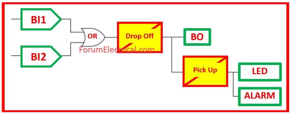
Note: Delay in the drop off must be provided to minimize false alarms due to voltage dips caused by fault in another section.
Testing Procedure of Trip Coil Supervision Relay
Task
Test all trip circuit supervision relays for the breaker trip circuit supervision in open & closed positions.
Preconditions
- The process of erection has been accomplished.
- Labeling of the aforementioned equipment
Precautions
- Follow ESD safety guidelines when handling electronic components.
- Make special safety preparations for locations not marked as “electrical operating areas” for testing at voltages above 50V.
Scope
- Testing the cable connections.
- Verify that the mounting location is proper.
Visual Inspection
- Checking the cables for any damage & ensuring they are properly attached.
- Check for physical connection per authorized drawings.
- Check for correct connection tightness.
Testing the Trip Circuit Supervision (TCS) Relay
The relay can be examined using a single phase (1Ø) secondary injection test set located on the front panel.
Enter the rating plate data into checklist & compare the relay data to the information in the circuit documentation.
The following test will be carried out.
Electrical Function Test
Functional Check of Test Plug
The Test Plug must be examined for proper function. Terminals should be verified for their accurate, auxiliary power & tripping arrangement according to the circuit diagram.
Secondary Injection Test
A connection is established between the relay and the secondary injection set.
Voltage Pick-up Verification Test
- Gradually increase the voltage till the relay picks up.
- Capture the voltage.
Voltage Drop-Out Verification Test
- Slowly increase voltage till the relay picks up.
- While the relay is still picking up, gradually reduce the power until it.
- Measure the dropout voltage.
Function Check
All internal & external wiring should be complete.
When the CB is in the Open Position
- The coil circuit is tripped at the control panel or box.
- The trip circuit supervision (TCS) relay should work.
When CB is in the Close Position
- Check the CB control panel or box for an open tripping coil circuit.
- The trip circuit supervision (TCS) relay should work.
Documentation
A test sheet must be completed for every trip circuit supervisory relay.
