
Electrical Substation
In modern times, the need for electrical power is steadily increasing. To accommodate this demand, we require larger power plants, which might be hydroelectric, thermal, or nuclear.
These stations are constructed at a variety of sites depending on resource availability, frequently distant from regions where electricity is used.
As a result, electricity must be transmitted from producing stations to load centers via high-voltage networks.
Power is produced at low voltages and transported at high voltages to maximize efficiency. Consumers get lower volts.
To maintain & stabilize these voltage levels, we need transformer and switching stations known as electrical substations. These substations are grouped according to their uses.
What is a Substation Layout?
The layout of the substation primarily comprises the overall substation layout and the layout of the
- High-voltage distribution room,
- Low-voltage distribution room,
- Transformer room,
- Control room,
- High-voltage capacitor room,
- Duty room, and
- Auxiliary rooms.
Substation Layout Requirements
Safe and easy operation, maintenance, inspection, and testing.
Take use of natural sunlight and ventilation. The transformer and capacitor rooms should avoid sunshine, while the control room must face south (distribution panel and table).
The substation design should be compact and practical, with easy access & exit cables for the transformers, buildings, & rooms. The high-voltage distribution room must be convenient for incoming & outgoing lines, the low-voltage distribution room must be near the transformer, and the high-voltage capacitor room should be connected to it.
A single level should be used for the 110 KV substation configuration. In a two-floor substation arrangement, the transformer should be on the bottom level & the power distribution room on second floor must contain lifting holes and a platform.
When designing a substation, the control room, duty room, & auxiliary room must be easily accessible to operational staff.
Fireproof walls with door apertures should be built at busbar sections when the same substation configuration powers the primary load. If the two cables delivering the primary load power cannot be separated, they should be flame-retardant and installed on brackets on either side of the cable trench.
To prevent rain, snow, & small animals from entering transformer, high and low voltage distribution, and capacitor rooms, illumination windows, ventilation windows, doors, cable trenches, and cable protection tubes should be installed.
Allow for spare intervals and growth in high & low voltage power distribution and transformer rooms. When designing substations, there should be enough spare switch cabinet (panel) positions in high and low voltage power distribution rooms, and the transformer outline should be one level greater than its capacity.
In an interior substation, each 3-phase transformer with one hundred kilos or more oil capacity should have its own transformer room.
Control rooms, duty rooms, high-voltage (HV) & low-voltage (LV) power distribution rooms, etc. must be 150–300 mm above ground. When affixed to a building, it might be flush with the floor.
High- and low-voltage power distribution, transformer, & capacitor rooms must have open doors. Doors connecting power distribution rooms must be opened in either directions (or) in the low-voltage direction.
Avoid doors and windows facing corrosive gas, dust, and noise in often opened rooms.
Principles of Substation Layouts
The basic concept of substation layout is to arrange a number of switchgear components in an orderly way determined by their function and spatial separation requirements.
Spatial Separation
- Earth Clearance – Earth Clearance is the clearance across live components and earthed constructions, walls, screens and ground.
- Phase Clearance – Phase Clearance is the clearance across live components of distinct phases.
- Isolating Distance – Isolating Distance is the clearance across the terminals of an isolator & the connections
- Section Clearance – The distance between a work section’s terminals and live components is known as section clearance.
Substation Layout
A substation’s dependability is determined by how well it provides supply security. In an ideal substation, every circuits & equipment must have a duplicate so that a connection is still accessible even during maintenance or fault circumstances.
However, supplying duplicates for every equipment, from the smallest power devices to the most significant, would be extremely expensive.
To be practicable, measures for ensuring supply security have been implemented at the lowest feasible investment cost. Substations are classified into four types :
- Category 1: No outages are required inside the substation for maintenance or fault circumstances.
- Category 2: A short outage is required to shift the load to a different circuit for maintenance (or) fault situations.
- Category 3: The failure of a circuit or segment of the substation due to a fault or maintenance.
- Category 4: Total substation failure due to a malfunction or maintenance.
To attain the needed dependability, many substation layouts were designed. These layouts are given in the most understandable form possible: one-line diagrams of the switching and protection arrangements, and also the incoming supply lines and exiting feeders. Incoming lines will typically have
- Disconnect Switch &
- Circuit Breaker.
Both function to isolate a component of the system during an emergency.
Moreover, circuit breakers are specifically designed to automatically terminate fault currents.
Current transformers may detect massive amounts of flowing current. These transformers’ outputs trip the breaker, allowing loads beyond the system to run with minimum consequence in the event of a breakdown.
The location of switches, circuit breakers, & buses varies across layouts. The correct balance of cost and reliability concerns will guide the selection on which layout to apply.
The following substation configurations will be reviewed and compared:
- Single Bus
- Sectionalized Buses
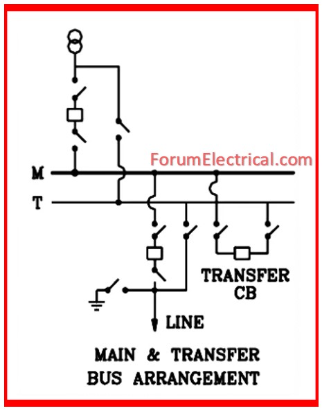
- Main and Transfer Buses
- Ring Bus
- Break-and-Half Bus
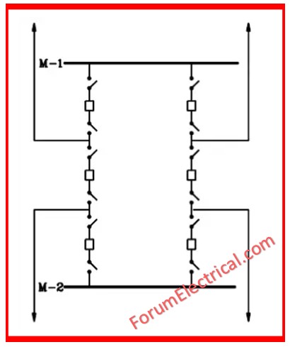
- Double Breaker/Double Bus
Single Bus
This is the simplest design, but it also has the lowest reliability.
It may be built in either a low-profile or high-profile configuration, depending on the total amount of space accessible.
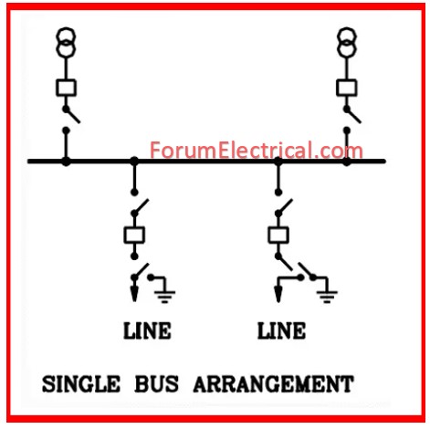
In the setup, the circuit should be de-energized to undertake breaker maintenance, which may be circumvented by the inclusion of breaker bypass switches, although this may then destroy protective systems.
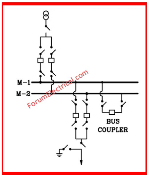
Sectionalized Bus
The single bus setups are now joined together using a central circuit breaker that can be typically open or closed.
Now, in the case of a breaker failure (or) bus bar fault, the complete station is not shut down.
Breaker bypass action may also be added in the sectionalized bus design.
Main and Transfer Buses
There are two distinct and independent buses: the main and the transfer. Usually, all circuits, incoming & outgoing, are connected to the main bus.
Ring Bus
The design of a ring bus arrangement, which is an extension of sectionalized bus.
In the ring bus, a sectionalizing breaker has been installed between the two open bus ends.
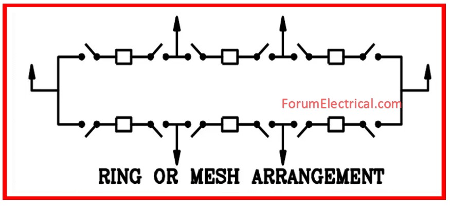
The bus now forms a complete loop, with each piece isolated by a circuit breaker.
This increases dependability and allows for more flexible functioning. The ring bus is readily adaptable to a breaker-and-half arrangement.
Breaker-and-Half Bus
A breaker-and-a-half system includes two buses, but unlike the main & transfer schemes, both buses are turned on during normal operation.
Any breaker may be removed for repair without interfering with service on the matching departing feeder, and a defect on either bus may be isolated without disrupting service on the outgoing line.
If a center breaker fails, two circuits are lost, but the loss of an outer breaker disrupts just one.
The breaker-and-a-half system is a common alternative for adding terminals to a ring bus.
Double Breaker Double Bus
The double breaker-double bus design, similar to the breaker-and-a-half, has two primary buses that are both typically powered.
However, each circuit needs two breakers rather of one and a half.
With the additional breaker per circuit, any of breakers may fail while only affecting one circuit.
This increased dependability comes at the expense of more breakers, therefore it is typically utilized primarily at large generating plants.
Major Substation Tasks
There are several works involved with substations in the distribution & transmission system.
Some of the key responsibilities that substations accomplish are as follows.
- It serves as the transmission system’s protection hub.
- It keeps the frequency of system restricted in desired limits and needs to cope with load shedding.
- It controls the exchange of electrical energy among consumers and generating stations.
- It ensures both transient stability and steady-state stability of the system.
- It provides sufficient line capacity consequently securing supply.
- It helps to reduce the flow of reactive power, allowing for voltage control.
- Through line carrier, it provides data transfer to guarantee monitoring of network, protection, & control.
- It supports in fault analysis and identifying reason for a failure, thereby enhancing the performance of electrical network.
- It ensures reliable supply via feeding network at the numerous points.
- It supports in determining energy transfer with assistance of transmission lines.


