
- What are Three Phase (3-Phase) Systems?
- Three Phase Motor Test
- Three-phase Motor Test Connection Diagram
- Different Types of Testing for Three-Phase Motors
- 1). General Inspections
- 2). Continuity Tests
- 3). Power Supply Test
- 4). AC Motor Winding Continuity Test
- 5). Insulation Resistance Test
- 6). Running Amps Test
- 7). Open Circuit Test
- 8). Short Circuit Test
- Different Types of Testing Methods
- 1). Lamp Testing Methods
- 2). Multimeter Test Methods
- 3). Megger Test Methods
- What is Motor Type Test?
- What is Motor Load Test?
What are Three Phase (3-Phase) Systems?
Phase systems are power supplies that utilize alternating current and are classified according to how many phases they possess.
Dual-phase, sometimes known as split-phase power, is made up of 2 alternating currents delivered by two wires, whereas single-phase electricity provides 1 phase at 120 volts.
Three single-phase AC supplies define a power circuit type known as three-phase power.
Three-phase power arrangements provide 1.732 times more electricity on the same current as single-phase power, making the system cheaper generally.
Three-phase systems are developed differently to meet different requirements.
Ex: A wye design may be utilized when a power supply must feed both single-phase & three-phase demands, such as lights & heaters.
The amount of power might also vary. Most commercial buildings utilize 208 Y / 120 V systems to increase flexibility in feeding both high-power & low-power loads, whereas industrial plants employ 480 Y / 240 V setups to enhance power availability for high-powered machinery.
IEC 60034 standards cover the design, performance, & testing of rotating electrical machines, particularly three-phase motors. It tests motor efficiency, temperature rise, & insulation resistance.
Three Phase Motor Test
Three phase motors are frequently utilized in house, residential, industrial, and commercial applications.
We use several types of motors, but when one of them fails, we inquire what went wrong.
If the motor fails to perform properly, it will need to be tested. After testing, we can learn about the current state of motor health.
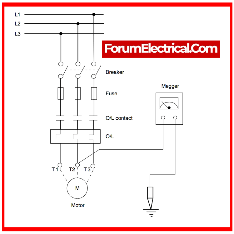
Three-phase Motor Test Connection Diagram
Different Types of Testing for Three-Phase Motors
If a three-phase motor fails to start, overheats, or has an irregular supply, you can examine it using a wide range of testing instruments and methods. The tools & methods are explained below.
However, before you conduct motor testing, make sure to follow all necessary safety precautions. This includes:
Wearing protective safety gear: It include grounding straps, gloves, & other environmental protective gear.
Keeping all tools easily accessible: Popular testing tools include multimeters, clamp meters, temperature sensors, and oscilloscopes. Having this equipment on hand may help us prevent leaving the motor unattended.
Disconnecting the motor from supply: When you’re all set, move the transformer’s motor disconnect switch to turn it off. Make sure the electricity is turned off – on certain motors, the disconnect switch is identical as the on/off switch, so turning it on will power the motor. Also, disconnect all equipment & wiring that will not be used in the testing process.
Discharge before & after testing: Before starting testing, and after each electrical test, discharge the motor, which has an inherent capacitance. This can be performed by connecting wires to ground and to each other before rejoining.
Check the nameplate: The nameplate (or) motor specifications contain essential information about the motor, such as its intended amperage. This information can be utilized to examine the motor’s health in relation to its intended design.
At this step, get your multimeter ready for testing. This involves setting the multimeter to measure AC voltage and adjusting the voltage range to an appropriate level based on the box’s specifications.
This tool will be used extensively in the following three-phase motor tests; thus, we will describe how to test a 3-phase motor with the multimeter.
1). General Inspections
The most fundamental type of inspection is visual. Once the motor has been turned off and you are ready to begin the inspection, remove the motor cover.
When this is removed, we can start to inspect the motor for visible signs of damage. A few aspects to look out for during this procedure are:
Step-1: General damage is easy to see. This may take the appearance of burn marks (or) indentations. Check the motor for any signs of heat (or) environmental damage.
Step-2: Manually rotate the motor shaft to check its condition. This should be simple, except the motor is particularly huge. The shaft must rotate smoothly, without any catches or loose components.
Step-3: Newer motors can have difficulties rotating because of tight tolerances, inactivity, (or) ambient moisture, that can be remedied with oiling and additional examination. However, older motors can have additional problems that require repair or replacement.
Step-4: Check all of the connections inside the motor for signs of wear or damage, and inspect any wires outside the motor for potential breaks.
Step-5: Any broken wires must be handled & replaced with care.
Step-6: Once the motor has passed a general inspection, verify your inspection instruments and start troubleshooting its electrical qualities.
2). Continuity Tests
- Continuity testing measures the resistance across two points.
- If the resistance is low, the two points are connected to electricity. If the resistance is high, the circuit is open.
- The earth continuity test establishes if the motor is linked to the ground.
- To complete the earth continuity test, switch the multimeter to continuity mode.
Once done, put one point on the motor’s frame and the other on a known earth connection, preferably in close proximity to the motor installation. A decent motor should give a reading of less than 0.5 Ω.
If the value is larger than 0.5 Ω, it indicates that the motor’s insulation is failing & could cause an electric shock. Identifying the causes of this failure can require additional testing.
3). Power Supply Test
The next test that must be performed is the power supply test. This ensures that the incoming power supply works as expected and meets the motor’s design parameters.
- The power supply test may be performed by measuring the voltage applied to the motor using a multimeter.
- Check this with the parameters listed on the nameplate.
- If the applied voltage is much lower or greater than indicated, this could be the root of the complications.
In addition to this test, ensure that the power supply terminal is in perfect condition. Damage and inadequate connections could also be responsible for any variations or performance concerns.
4). AC Motor Winding Continuity Test
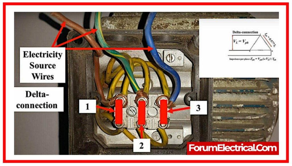
- Check the interior of the motor and the cables that carry the three-phase current.
- Set & calibrate your multimeter for voltage, then locate the 6 wires of the three-phase motor.
- When checking at the box, one should notice six cables, 3 on each side. The wires should be attached to terminals on every side of the box.
- On one side, terminals will be labeled L1, L2, and L3, or Line 1, Line 2, and Line 3. The terminals on the other side will be designated T1, T2, and T3, which stand for Load 1, Load 2, and Load 3.
- L terminals represent line wires carrying incoming current, and T terminals represent outbound wires.
- The only exception is European motors, which will be designated U, V, and W.
These cables should be examined to establish the condition of the motor’s power supply.
This may be assessed via the methods listed below:
No Power Incoming Test: While the box is turned off, set the multimeter probes on various combinations of the L terminals to measure the incoming voltage. Take a reading on the L1 to L2 connection, L1 to L3 connection, and L2 to L3 connection. These readings must be identical if the motor is functioning properly. For a 230/400V system, the predicted voltage between each three-phase supply line is 400V.
Line to Neutral Test: If a neutral terminal is accessible, connect one multimeter probe to it and one to each of line terminals. The voltage value must be half of the value that was measured during the last test.
No Power Outgoing Test: This test is identical to the one above, but it measures the outgoing voltage. While the box is still off, measure the distance between the T1 & T2 leads, T1 and T3 leads, and T2 and T3 leads. In this situation, the voltage reading must be 0 for all tests.
Power Outgoing Test: Very carefully turn on the box & repeat the foregoing tests, testing each combination of the T leads. Each lead combination should be nearly identical.
If the readings vary from the expected results & the power supply test revealed no difficulties, the three-phase AC motor’s health may be compromised.
Typically, this implies that the motor has burned out.
5). Insulation Resistance Test
The next step in determining the motor’s overall condition is to perform an insulating resistance test.
This is accomplished by measuring the resistance across each pair of motor phases & between every motor phase & the frame.
This can be accomplished using an insulation tester (or) megger.
Tests should be completed as follows:
- Phase Resistance: Set the insulation tester at 500 V. Take each end & place it on a different combination of L1, L2, and L3, recording each reading.
- Phase to Earth Resistance: Using the same setting on the insulation tester, examine each lead from the phase to the motor frame. The minimum insulation resistance must be 1 MΩ. If the resistance is less than 0.2 MΩ, replace the motor.
Any faults discovered throughout this round of testing may suggest insulation difficulties which are important to the motor’s safety and functionality.
According to IEEE Standard 43-200/43-2013, insulation resistance readings across all motor types, voltages between 0 & 1000 VAC, phase, & HP should normally fall within the ranges.
6). Running Amps Test
The final test indicates the amount of energy is required to drive the motor. More stronger motors will consume more current (measured in amps).
Before testing, make sure your motor’s amperage draw is correct; this is normally indicated on the nameplate.
When ready, follow the steps below to learn how to measure 3-phase current.
Step-1: Prepare for the test: Set the multimeter up to measure amperes and adjust it to the appropriate ampere range for the motor based on the specifications on the nameplate. To avoid electric shock, wear rubber hands during the test.
Step-2: Turn on the motor: Start the motor & locate the terminals. The positive terminal shall be identified with a plus symbol & attached to a red cable. The negative terminal shall be identified with a minus symbol & attached to a black cable.
Step-3: Place the Sensors: Connect the multimeter’s negative sensor to the motor’s negative terminal, followed by the positive sensor. To avoid harm, always keep your hands away from moving parts.
When the sensors have been connected, they measure the amperes & switch off the motor.
If everything is working properly, the ampere reading needs to be within the acceptable range.
The ampere reading should not exceed the manufacturer’s specification, but rather be at (or) slightly below the stated amperage consumption.
If the ampere value is significantly below specification (or) out of range, it could indicate a problem with the motor.
7). Open Circuit Test
Open circuit tests are performed on both running and starting windings. After this, we can determine whether both windings are open or closed.
This test may be performed in two ways: with a testing lamp or with a multimeter.
8). Short Circuit Test
Short circuit testing is performed on both the starting and running windings. Following this, we may determine whether both windings are short or not in the body (or) each other.
This test can be performed in two ways: with a testing lamp or with a multimeter.
Different Types of Testing Methods
Testing methods include identifying faults when a motor fails to function properly.
There are three types of motor testing procedures available, as indicated below.
- Lamp testing methods.
- Multimeter test methods.
- Megger test methods.
1). Lamp Testing Methods
- A three-phase motor will be examined either when it is malfunctioning or after it has been rewinding.
- In order to test or verify a three-phase motor, there are several different ways available.
- One of the most used testing methods is the testing lamp method.
- It is a circuit for testing instruments that connects in series with equipment that is considered to be fault.
2). Multimeter Test Methods
- Multimeter testing of a three-phase motor provides different methods to assure proper operation.
- To verify healthy windings, measure the resistance between every pair of motor terminals.
- No open circuits should be found during a continuity test of the motor’s internal connections & windings.
- Insulation resistance tests can also detect motor winding insulation breakdowns.
- Finally, testing voltage levels throughout each phase while the motor is running may identify power supply faults or phase imbalances that could influence motor performance.
- These multimeter tests completely evaluate the three-phase motor and helps identifying any faults.
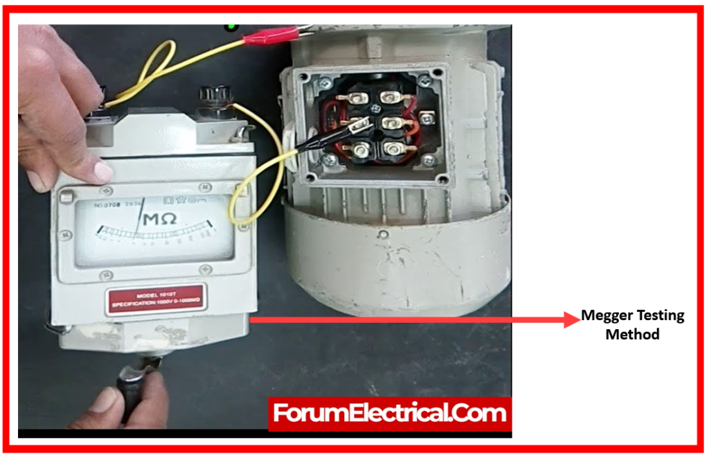
3). Megger Test Methods
- Three-phase motor insulation durability is assessed by megger testing using high-voltage insulation resistance measurements.
- High voltage is applied across the motor windings & frame, then current flow resistance is measured.
- This test detects insulation faults that could affect motor performance (or) safety.
- Megger testing helps determine insulation repair or replacement to prevent malfunctions or electrical risks.
- This testing instrument is essential for three-phase motor system reliability and longevity.
What is Motor Type Test?
The type test system evaluates 3-phase AC traction & induction motor performance at the manufacturing location by performing full-load tests. Motor parameters are measured by sensors and powered by relevant sources.
What is Motor Load Test?
The primary function of load testing is to ensure that the motor delivers torque matching nameplate specifications such horsepower/kilowatts, speed, voltage, and current. Commutation (to ensure no sparking at brushes) is another important factor for DC motors.