
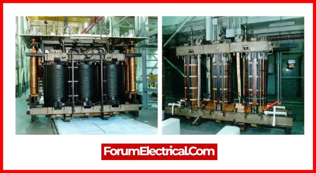
In this post, we are going to discuss about transformer faults & protection schemes. The transformer is an essential electrical device in the electrical power system, used to step up and down voltage & current in the transmission lines.
If a failure arises in the system, the transformer needs to be disconnected as soon as possible; otherwise, it may be damaged. In this post, we will look at several types of transformer faults and transformer protection schemes.
What are Transformer Faults?
Typical distribution transformer faults include winding failures such as
- Dielectric faults,
- Copper resistance thermal losses,
- Mechanical faults in winding distortion,
- Failures of the bushing, tap changer, core, tanks, protection systems, cooling systems, etc.
Cause of the Transformer Faults
An electrical power transformer is static, but inappropriate system conditions might cause internal variations.
A transformer usually has these faults:
- Overcurrent from overloads & external short circuits
- Terminal faults,
- Winding faults,
- Incipient faults.
All the previously mentioned transformer faults stress the winding and terminals mechanically and thermally.
Overheating from thermal pressures damages transformer insulation. Winding issues result from insulation degradation.
Transformers can overheat when their cooling systems fail. Transformer protection schemes are essential.
The reactance of an electrical transformer limits its short circuit current, which might be excessive for low reactance.
The BSS 171:1936 duration of the external short circuits a transformer may withstand without damage.
| Transformer % Reactance | Fault Duration (seconds) |
| 4 % | 2 |
| 5 % | 3 |
| 6 % | 4 |
| 7 % | Above 5% |
Transformer winding faults are usually earth or inter-turns.
Transformer phase-to-phase winding errors are infrequent.
- Bushing flash over &
- Tap changer faults
can cause transformer phase faults.
In any problem, the transformer needs to be separated immediately to prevent a power system breakdown.
Internal defects that are not dangerous are incipient. However, neglecting these errors might cause serious faults. Insulation failure between core lamination causes
- Inter-lamination short circuits,
- Oil leaking lowers oil levels, and
- Oil flow pathways
are blocked.
All these faults cause overheating. Incipient transformer problems necessitate transformer protection.
The earth fault near the transformer star winding neutral point may also be an incipient fault.
Winding and earthing affect earth fault current magnitude.
Two basic criteria allow earth fault current to flow while winding to earth faults.
- A current exists for the current to flow into & out of the winding.
- Ampere-turns balance is maintained (balanced) across the windings.
Winding earth fault current depends on
- Fault position,
- Winding connection, and
- Earthing.
Earth the windings’ star point securely or via a resistor. An earthing transformer earths the delta side of transformer.
Grounding or earthing transformers have low impedance for zero sequence current and high for positive & negative sequence currents.
Types of Transformer Faults
Transformer faults fall into three categories based on where they occur:
- Faults in transformer winding & connections,
- Faults in the auxiliary equipment of the transformer,
- Faults due to overload & external short circuits.
Each transformer fault category will be discussed in detail.
1). Faults in Transformer Winding & Connections
Unbalanced current causes transformer winding and connection failures. Due to their quick transformer winding damage, these defects are severe. These faults include phase-to-phase, phase-to-earth, etc.
Transformer inter-turn short circuits are caused by insulation failure (or) mechanical pressures.
Short circuits create heavy current flow across windings, which decomposes transformer oil and emits a lot of gas. While these defects are easily detectable, they must be addressed immediately to prevent transformer damage.
Neutral-Resistance Earthed Star Winding
- The transformer’s neutral point is earthed via a resistor, which has a much higher impedance than its windings.
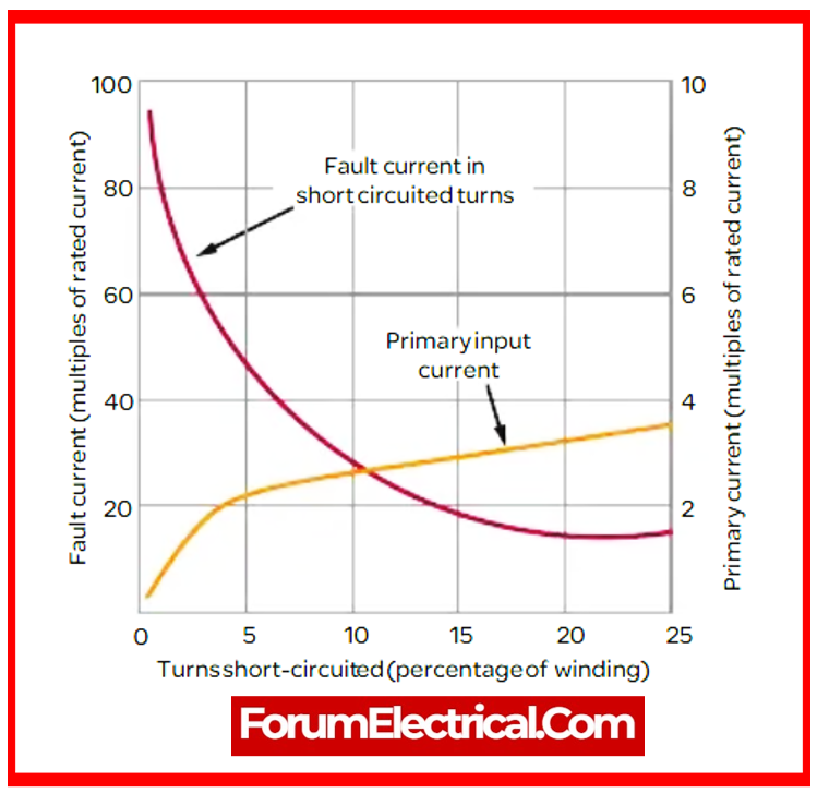
- It means transformer winding impedance is small compared to earthing resistor. Thus, earth current is proportional to winding fault position.
- The primary fault current in transformers is proportional to the square of winding short circuit percentage, which is the ratio of short-circuited secondary turns to total turns on the primary winding.
Neutral Solid Earthed Star Winding
- The winding impedance limits the earth fault current magnitude, so the fault is no more proportionate to its position.
- Unbalanced flux linkage causes nonlinearity.
2). Faults in the auxiliary equipment of the Transformer
Transformer Auxiliary Equipment Faults
- Transformer auxiliary equipment like insulation, transformer oil, conservator tank, etc. fail.
- These faults can harm transformer windings. Thus, these defects must be found and fixed quickly.
Insulation Failure Faults
- Transformer failure due to core and winding insulation failure generates severe failures.
- This fault is caused by insufficient insulation, overcurrent flow, etc.
Gas Cushion Faults
- Oxygen and moisture affect transformer insulation and oil.
- The conservator tank & breather must work properly to avoid oxygen and moisture.
Transformer Oil Breakdown Faults
- Transformer oil cools and insulates. To avoid transformer failures, oil temperature and insulation must be maintained.
3). Faults due to Overload & External Short Circuits
Heavy currents pass through transformer windings due to overload & external short circuits. Failure of insulation occurs. To avoid transformer faults, we need to reduce system overload & external short circuits.
What is the Protection Scheme of Transformers?
Transformer protection’s primary objective is to identify internal faults in transformer with extreme sensitivity, de-energize the transformer as a result, and simultaneously protect it from external faults, or through-failures.
Transformer Protection Schemes
Basic safety features such as
- Overexcitation protection and
- Temperature-based protection
can detect conditions which ultimately lead to a fault condition, but complete transformer protection made possible by relays and current transformers is ideal for transformers in essential applications.
Transformer Protection for Different Types of Transformers
The type of protection technique employed on a power transformer is determined by its category. The table below demonstrates that:
| Category | Transformer Rating (KVA) | |
| 1 Phase | 3 Phase | |
| I | 5 – 500 KVA | 15 – 500 KVA |
| II | 501 – 1667 KVA | 501 – 5000 KVA |
| III | 1668 – 10000 KVA | 5001 – 30000 KVA |
| IV | > 10000 KVA | > 30000 KVA |
Transformers up to 500 KVA are classified as (Category I & II), and they are protected with fuses; however, medium voltage circuit breakers are typically used for protecting transformers of up to 1000 KVA (distribution transformers for 11kV & 33kV).
Differential relays were required to protect transformers with a power rating of 10 MVA or more, which are classified as Category III and IV.
Furthermore, mechanical relays that include Buchholtz relays & sudden pressure relays are commonly used for transformer safety. Along with these relays, thermal overload protection is frequently used to lengthen a transformer’s life rather than to identify faults.
Types of Transformer Protection Schemes
Transformer protection schemes vary depending on the transformer’s size and rating.
The following explains some popular transformer protection techniques.
1). Buchholz Relay
2). Overheating Protection for Transformers
3). Differential Protection
4). Overcurrent Protection in the Transformer
5). Harmonic Restraint Relay
6). Over-Fluxing Protection
7). Restricted Earth Fault Protection
8). Sudden Pressure Relay
9). Lightning Protection
1). Buchholz Relay
Buchholz relay is a gas-powered relay and also referred as gas detection relay. Under normal operation, the Buchholz relay is entirely filled with oil. When a fault occurs, gas bubbles emerge in transformer tank. The gas gradually accumulates in relay chamber.
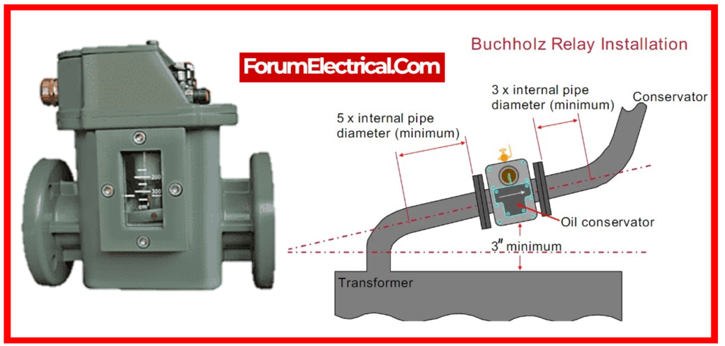
Buchholz relays can detect both minor and significant transformer failures. Minor faults trigger an alarm, while major fault events trip the circuit.
2). Overheating Protection for Transformers
Transformers overheat because of overloads and short circuits. The permissible overload and duration depend on the transformer type and insulation class.
Higher loads might be sustained for a very short period of time; but, if they are maintained for an extended period of time, the insulation may be damaged owing to increases in temperature above an estimated maximum.
The maximum temperature of an oil-cooled transformer is 95°C, after which the transformer’s life expectancy declines and the insulation of the wire deteriorates.
The thermal overload function (ANSI/IEEE/IEC code 49) is the most commonly provided feature for thermal protection of the power transformers.
That is the reason overheating protection is essential.
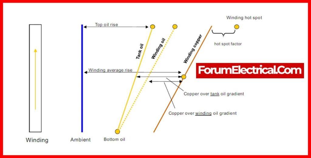
Large transformers have oil or winding temperature detection devices that measure oil or winding temperature.
There are typically two methods of measurement:
- Hot-spot measurement and
- Top-oil measurement.
3). Differential Protection
The differential protection technique protects the transformer from
- Phase-to-phase faults and
- Phase-to-ground faults.
It is also known as “circulating current protection.”
Differential protection operates by comparing currents passing through the transformer’s primary and secondary windings.
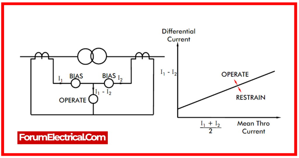
When the incoming current equals the output current, it indicates that there is no problem inside the transformer.
When a fault occurs within the transformer, the transformer’s outgoing current cannot be identical to the entering current since the current has taken a different course.
Thus, when the differential protection relay detects that the current difference exceeds the predetermined limit, it activates the circuit breaker.
The differential protection technique protects the transformer against winding short circuits and inter-turn failures.
This is accomplished by means of “differential protection” (ANSI, IEEE, and IEC code 87T).
4). Overcurrent Protection in the Transformer
The overcurrent protection system comprises one of the oldest protection systems accessible; the rated overcurrent system was designed to protect against overcurrent conditions.
Power distributors use this technology to detect defects with the help of IDMT relays. Specifically, the relays have:
- Inverse characteristic and
- Minimum operating time.
The capabilities of IDMT relay are limited.
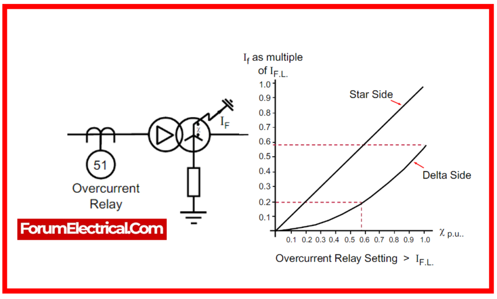
These kinds of relays must be set to 150% to 200% of the maximum rated current; otherwise, they will operate during emergency overload conditions.
As a result, these relays offer only limited protection against faults within the transformer tank.
5). Harmonic Restraint Relay
The harmonic restraint relay is utilized to protect the transformer from magnetizing inrush currents.
The series LC circuit used in this protection method forces all higher harmonic components of the inrush current to pass through the restraining coils while only the fundamental harmonic component can pass through the operational coil and the DC component.
While the transformer is charging, the second & fifth-order harmonics are blocked by the harmonic constraint relay.
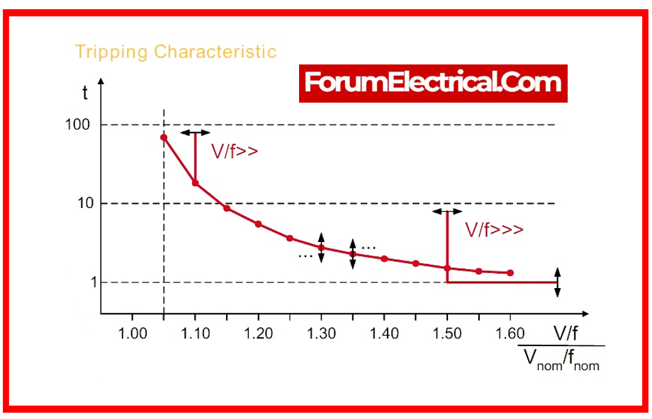
6). Over-Fluxing Protection
Excessive fluxing raises the transformer’s temperature and damages it.
In order to protect the transformer from excessive fluxing, a V/Hz over excitation relay is employed, which functions at an excessively high voltage or low frequency.
The flux in the core of the transformer stays equal to its intended flux density when it is operating at its rated voltage & frequency.
Over-fluxing, however, occurs whenever there is a variation from the design value of the voltage or frequency.
When the over-fluxing exceeds 110% of the rated value, the over-fluxing relay trips the circuit breaker by continually monitoring the V/f ratio.
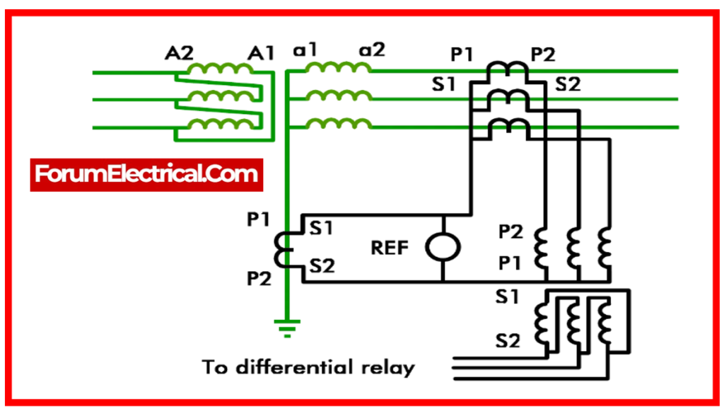
7). Restricted Earth Fault Protection
Transformer windings are protected against earth faults via restricted earth fault protection.
It serves as protection for the transformer in the area between the earthed neutral terminal and the start connected winding.
Neutral current and phase current transformers are used to execute the restricted earth fault protection.
One current transformer and all of the secondary windings of the CTs are connected in parallel in each phase.
The imbalance current or earth fault current is represented by the vector sum of the zero sequence currents, which is the ultimate output of all CTs.
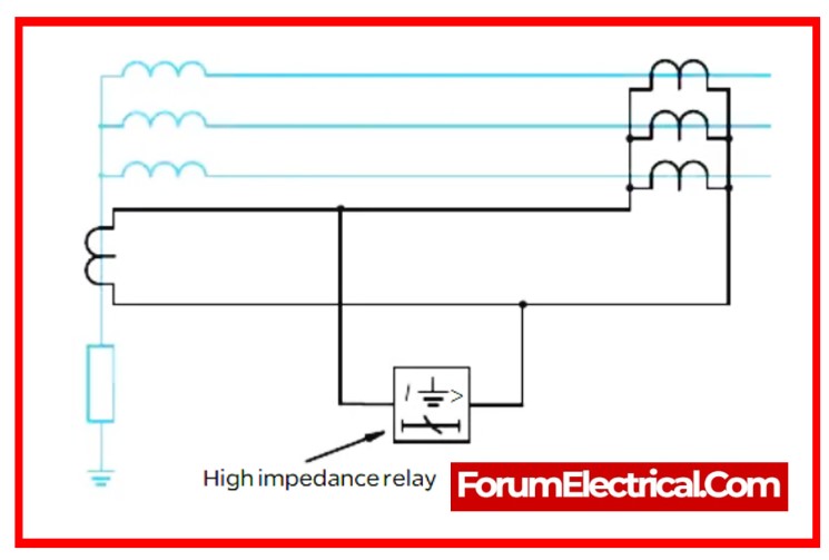
The three CT secondary windings are connected to the earth fault relay.
The relay does not choose in the condition when the vector sum of the line current equals the neutral current, which occurs when there is no fault inside transformer.
When a fault occurs, the current flowing in neutral CT cannot be equal to the vector sum of the line current; in this condition, the current differential trips the relay.
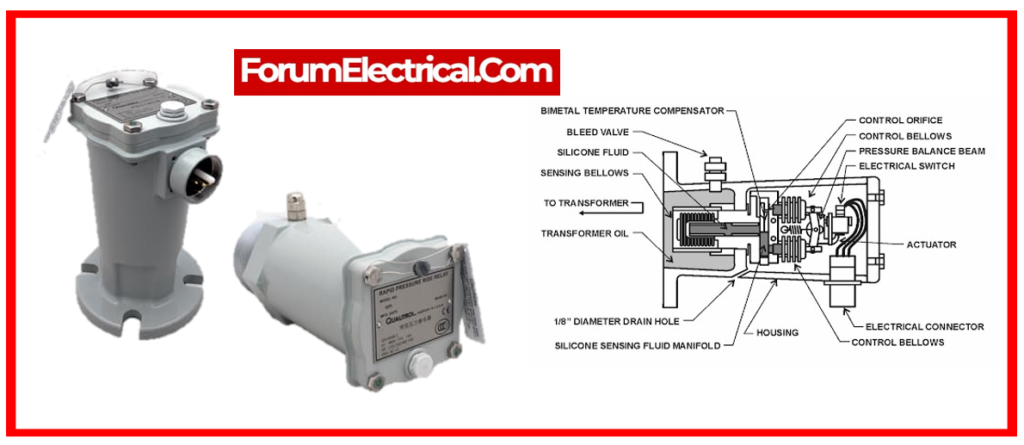
8). Sudden Pressure Relay
The transformer tank’s pressure is abruptly increased by internal arcing, which is prevented by the employment of the sudden pressure relay.
Internal transformer faults are the reason for the unexpected rise in tank pressure.
The tank may explode if the pressure builds up above the tank’s design capacity.
When the relay detects a sudden increase in pressure, it sends a trip order to the circuit breaker, cutting off the transformer’s supply.
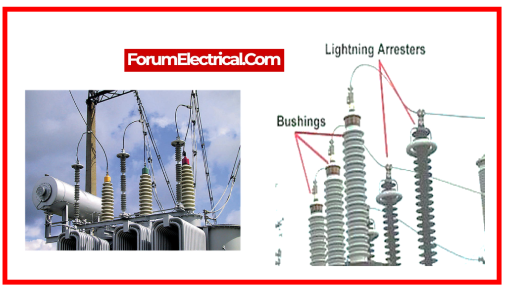
9). Lightning Protection
Surge arresters fitted in the transformer tank provide electricity transformers with lightning protection.
The most popular surge arresters are silicone rubber or porcelain-clad non-linear metal oxide resistors that are installed in parallel with the object being protected and connected to the ground grid.
Non-linear resistors have resistance that is inversely proportional to current, meaning that at high lightning discharge currents, the resistance is very low and at high service values, it is high.
