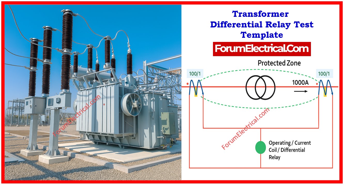
Introduction to Transformer Differential Relay Testing
Differential relay testing is one of the most important processes in maintaining the safe operation of power transformers in substations & industrial applications.
- Introduction to Transformer Differential Relay Testing
- Equipment and Transformer Specifications
- Relay Physical inspection
- Measurement & Status Verification
- LED Indicators & Signal Identification
- Relay Function Configuration
- HV Differential Function Test Results
- LV Differential Function Test Results
- Phase Overcurrent Function Test (DMT Mode)
- Residual Overcurrent Function Test (DMT Mode)
- Differential Stability Verification
- Verification
- Template
This testing method checks the relay’s accuracy, stability & sensitivity under various operating & fault conditions
The template below contains a full record of transformer differential relay tests, including CT data, power transformer specs, inspection results & functional test outcomes.
Equipment and Transformer Specifications
Before starting the test, all important information regarding the relay & transformer is documented.
The test report starts with the differential relay’s model, make & serial number as well as the place where it was installed.
Furthermore, current transformer (CT) measurements for both the HV and LV bushings are recorded including primary & secondary current values.
In addition, the transformer specifics are thoroughly recorded.
These include
- Power transformer’s rating,
- Rated primary & secondary currents based on specified MVA base,
- High-voltage & low-voltage ratings,
- Vector group design and
- % Impedance.
Relay Physical inspection
Before applying test signals, the differential relay undergoes a physical check to determine its condition.
The external look is checked for evidence of deterioration, cracks and wear. The front HME (Human Machine Interface) is checked for visibility & operational integrity & the keypad is verified for the response.
The status of the LED indicators is checked as well to ensure that they are properly operating and plainly visible.
Measurement & Status Verification
Several measurements and status checks are performed during the test to ensure that the wiring & relay response is correct.
Analog inputs such as CT currents are validated for proper scale and polarity.
Binary inputs (or) opto-coupler status are inspected for proper signaling from the external contacts, while binary outputs & command relay connections are tested for proper tripping and signaling function.
The HMI LED indicators are cross-checked to ensure that they match the intended signal mappings.
LED Indicators & Signal Identification
Each LED indication on the relay front panel is labeled and tested to ensure its accuracy. The
- Differential trip between the HV & LV sides,
- External trip signals,
- General overcurrent trip,
- Phase overcurrent trip and
- Residual overcurrent trip
Have all been proven.
This ensures that in the case of an actual failure, the LED indications assist operators with easy and accurate fault identification.
Relay Function Configuration
The differential relay is programmed with various protection features based on the transformer specifications.
The differential protection function (87T) is the key component that protects against
- Internal Phase-to-Phase &
- Phase-to-Ground Faults.
Additional options comprise
- HV Phase overcurrent function (51) &
- HV Residual overcurrent function (51N).
Each function is documented and assigned a serial number for easy traceability during future maintenance (or) troubleshooting.
HV Differential Function Test Results
The high voltage (HV) differential function is used to verified phase by phase.
Each test logs the set current (I/In), the actual operated current & the delay in relay operation.
Remarks are made to confirm that the relay answered within the intended range.
These findings support the differential relay’s capacity to detect defects on the transformer’s high-voltage side.
LV Differential Function Test Results
The transformer’s low-voltage side undergoes a similar differential function test.
Each phase is tested to ensure that the relay performs properly under fault current simulation.
The operating current, response time & any variations are recorded to ensure that the transformer’s LV side is equally protected from internal problems.
Phase Overcurrent Function Test (DMT Mode)
The phase overcurrent function is evaluated using the definite minimum time (DMT) criteria. Each phase: (R, Y and B) is applied with a specific current and time.
To ensure accuracy, the relay’s response is checked for both operating current and delay.
Proper functionality ensures that the relay will serve as backup protection against phase faults if differential protection is not activated.
Residual Overcurrent Function Test (DMT Mode)
Residual overcurrent protection is a most important backup feature for identifying the ground faults.
This function is also phase-tested with specified current and time parameters.
Operated current and reaction delays are recorded to confirm compliance with protection parameters.
Differential Stability Verification
An essential part of relay testing is demonstrating stability under normal working conditions & during external failures.
The relay is tested under load to verify that no unexpected tripping occurs. It is further evaluated against simulated external fault conditions to ensure that stability is maintained.
A relay that trips during stable load (or) external fault conditions indicates that the configuration is improper or that the CTs mismatch.
Verification
After all tests have been completed, the results are evaluated and certified. The testing engineer signs off on the test, which is then checked by an authorized supervisor.
This record verifies that the transformer differential relay is operational and ready for reliable service in protection of the transformer from internal defects.

