
- What is a Transformer?
- What is Tap Changer?
- System voltage management using Tap Changer
- Different types of taps
- OLTC – On Load Tap Changer
- Location of Tapping in OLTC
- OLTC Working Function
- Advantages of OLTC
- Disadvantages of OLTC
- Applications for OLTC
- Diagnosis of OLTC
- 1).Electrical field test of OLTC
- 2).OLTC Oil Test
- 3).Other Test
- DETC – De-Energised Tap Changer (Off Load Tap Changer)
- Application of DETC
- Why tap changer is required in a transformer?
What is a Transformer?
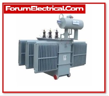
A transformer is an electrical device that includes the principle of electromagnetic induction to transfer energy from one electric circuit to another. It is designed to either increase or reduce the alternating current voltage between the circuits with maintain the current frequency. Transformers perform this with no conductive connection between the two circuits. This is accomplished because of the application of Faraday’s Law of Induction, which describes how a magnetic field interacts with an electric circuit to produce electromotive force (EMF).
What is Tap Changer?
A tap changer is used to control the output voltage of a transformer. It accomplishes this by adjusting the number of turns in one winding and so changing the transformer’s turns ratio.
Tap changer is classified into 2 types, they are
1). OLTC – On Load Tap Changer
2). DETC – De-Energised Tap Changer (Off Load Tap Changer)
It should be noted that not all transformers have tap changers.
System voltage management using Tap Changer
System voltage control is required for:
1. Keeping the consumer’s terminal voltage within the limitations specified
2. Voltage adjustment in response to changes in load.
3. To regulate both real and reactive power.
4. To adjust the secondary voltage dependent on the conditions.
Different types of taps
Principal taps can either be positive or negative, or both. A tap is considered to be principal when it is possible to acquire the rated secondary voltage for the rated primary voltage at that tap. Positive and negative taps are, as their names suggest, the points at which the secondary voltage is either higher than or lower than the voltage at the principle tap.
The HV windings of the transformer are equipped with taps at various points.
1. Since the high voltage winding has a large number of turns, it is possible to get a voltage variation with a high level of efficiency.
2. The current running through the large transformers of low-voltage windings is at a high level. Because of this, preventing high currents from flowing is a difficult challenge.
3. The low voltage winding is located closer to the core, whereas the high voltage winding is located on the exterior. As a result, installing taps on the high voltage winding is a relatively simpler process than applying them to the low voltage winding.
OLTC – On Load Tap Changer
On-load tap changers are used to adjust the turns ratio while keeping the load connected. Even when the transformer is delivering power, taps can be changed. On-load tap changers significantly improve system efficiency. On load tap changers are standard on all large power transformers.
The following are the reasons for including on load tap changers in power transformers:
1. The main circuit stays unaffected during the operation of on load tap changers.
2. Dangerous arcing is avoided.
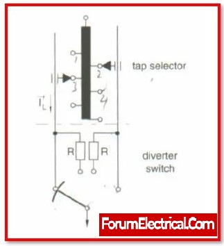
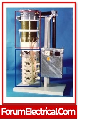
The taps on the windings are routed to a separate oil-filled chamber that houses the on-load tap changer switch. The tap changer is a type of mechanical selector switch that is controlled by a motor either locally or remotely.
A handle designed for manual operation in the event of an emergency.
The selector switch is a type of make before break switch, and a temporary connection must be created between the adjacent taps during the transition of the tap changers from one tap to another. As a result, a short circuit occurs between the adjacent taps. A resistor or reactor must be used to limit the short circuit current. As a result, all types of on load tap changers include an impedance to limit short circuit current during tap changing operation. The impedance could be resistance or a reactance with a central tap. It is always carried out by a pair of resistors in current systems.
Location of Tapping in OLTC
The tapping is done at the end of phase, in the winding centre, or at a point of neutrality. The placement of them at different locations provides the following advantages:
- If the tap is connected at the end of the phase, the bushing insulators can be minimised.
- If the tap is connected near the winding centre, the insulation between separate sections will be reduced.
This type of configuration is required for larger transformers.
OLTC Working Function
- Whenever a voltage change is required, the fingers A&B are brought to segment 2 by following the technique.
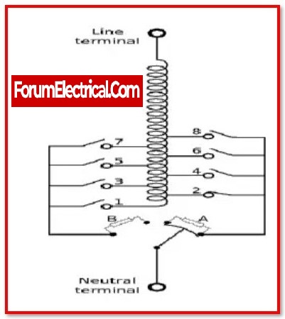
- Open switch y: because the entire current is now flowing via the lower half of the reactor, it becomes very inductive, resulting in a substantial voltage drop.
- As a result, the reactor must be constructed to temporarily handle full load current.
- Because switch y is open, the B finger carries no current. As a result, it can be transported to section 2 without sparking.
- After shutting switch y, the winding between taps 1 and 2 is linked across the reactor.
- Now, turn on switch x, and the entire current will begin to flow through the reactor’s upper half.
- Close switch x after moving finger A from segment 1 to segment 2. As a result, the transformer winding between taps 1 and 2 is no longer connected to the circuit.
- The same process of tap changes of the transformer is used for further voltage fluctuation.
Advantages of OLTC
- The voltage ratio can be changed without deactivating the transformer.
- Controls the voltage in the transformer.
- OLTC improves efficiency.
- It allows for the modification of voltage magnitude and reactive flow.
Disadvantages of OLTC
- The transformer utilised is more expensive.
- Highly maintenance
- Less dependability.
Applications for OLTC
- High Voltage Power Transformer used in power generation and >110KVA sub-stations.
Diagnosis of OLTC
1).Electrical field test of OLTC
Exciting current
Exciting current tests can detect a variety of transformer tap changer (DETC and OLTC) problems, such as misalignment, coking and wear of contacts, loose moveable contacts, improper wiring from the tap winding to the OLTC, reversed connections to an OLTC’s preventative autotransformer (PA), open- or short-circuited turns or high resistance connections, and more.
Resistance to DC windings
A DC winding resistance test is used to discover any fault that compromises the integrity of a winding’s current carrying channel between terminals, including the tap changer. It is very good at detecting partial open-circuit circumstances.
Resistance to dynamic winding
A dynamic winding resistance test measures the DC current and resistance while the tap position of the OLTC changes. It is especially useful for finding faults with a resistive style OLTC’s diverter switch, diverter switch contacts, and transition resistors. In general, the test evaluates the integrity of any component that generates, transports, or breaks current during an OLTC activity.
SFRA (sweep frequency response analysis)
The mechanical integrity of the tap windings and their leads is evaluated during a FRA test on a transformer in the mid- to upper-frequency ranges.
2).OLTC Oil Test
DGA
Normal gassing patterns (created as insulating materials deteriorate) differ for each OLTC family. DGA on an OLTC oil sample is a helpful technique for diagnosing problems such as localised overheating or excessive arcing, which will cause a shift in the OLTC’s typical gassing behaviour (for example, the ratio of the hydrocarbon gases change).
Strength of dielectric
Ensures that the dielectric breakdown voltage of the oil in the OLTC is greater than a certain threshold. The relative saturation of water in oil, as well as the presence of conductive particles, influence this (number and size).
Moisture
A test for excessive water in the tap changer, which lowers the dielectric breakdown strength of the oil and can hasten contact ageing.
3).Other Test
Infrared Test
Infrared detects temperature differences between the transformer’s main tank and tap compartment; it is unusual for the tap compartment to be as hot as or hotter than the main tank.
DETC – De-Energised Tap Changer (Off Load Tap Changer)
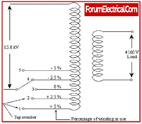
On the High Voltage side of the transformers, there is often a five-position off-load tap-changer with its handle positioned on the cover. It is necessary to de-energize the transformer before making any changes to the tap location.
Position 1 of the tap-changer (+ position symbol) corresponds with the highest ratio, which results in the lowest voltage on the Low Voltage side.
Position 5 of the tap-changer (- position symbol) corresponds with the lowest ratio, which as a result provides the maximum voltage on the Low Voltage side. Transformers that have two primary voltages (or two secondary voltages) typically have a selector switch mounted on the cover of the device, and the switch’s handle is located on the cover.

When the transformer is energised, the tap changer on a DETC cannot be changed in any direction while the transformer is operating. Frequently, it has 5 positions (A, B, C, D, E, or 1,2,3,4,5). If a DETC is not used on a regular basis, there is a greater chance that it will not function correctly when it is changed for the next time.
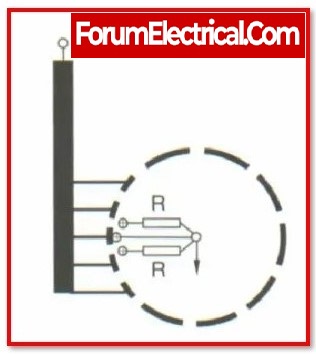
The Off-Load Tap Changer is used to compensate for seasonal variations in voltage. The figure below is a typical simplified diagram of an Off-Load Tap Changer.
The winding is tapped from six positions, as shown in the image above, for which six studs are provided. Six studs are positioned around the circumference of a circle. A hand wheel located outside the Transformer Tank can be used to rotate the rotatable arm R.
If the windings are tapped at 2.5% intervals, then
- If the rotatable arm is at stud 1-2, the entire winding is closed.
- When the rotatable arm is at stud 2-3, 97.5% of the winding is in circuit.
- If the rotatable arm is at stud 3-4, 95% of the winding is in circuit.
- When the rotatable arm is at stud 4-5, 92.5% of the winding is in circuit.
- If the rotatable arm is at stud 5-6, 90% of the winding is in circuit.
Thus, the voltage of the secondary is determined by the location of the rotatable arm R. An additional Stud Stop is supplied to ensure that Rotatable arm R is not rotated farther clockwise, otherwise the studs 1-6 will be shorted, resulting in only the lowest part of the winding being cut out, resulting in undesired mechanical stress.
Because Off-Load Tap Changing is not a Make Before Break type, it must be ensured that the Transformer is de-energized. Heavy sparking will occur if the Off-Load Tap Changer is operated while the Transformer is active, causing damage to the winding and insulation.
Application of DETC
Distribution Transformer ranges from 250 KVA to 500 KVA
Why tap changer is required in a transformer?
The transformer voltage at the load side should be constant or close to the design value.
However, the load voltage can change depending on the current drawn by the load (or) the supply voltage.
V1/ V2 = N1/ N2
Hence,
V2 = V1/K
Where,
K=N1/N2
To maintain a constant secondary voltage/load voltage (or) close to the required value, adjust the turn ratio as shown in the equation above. The secondary voltage (V2) and turns ratio (K) of the transformer are inversely proportional. A tap changer regulates the output voltage of transformers. Changing the number of turns in one winding changes the transformer’s turn ratio.