
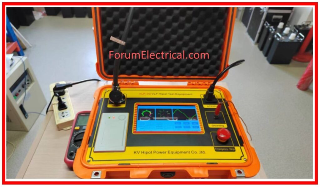
What is VLF Testing?
Very Low Frequency (VLF) testing is a method for determining the integrity of insulation in cables & other electrical equipment.
VLF testing utilizes frequencies between 0.1 Hz & 0.01 Hz, which differs from the regular electrical power frequency testing.
This lower frequency reduces stress on insulation while still detecting faults or problems.
During the test, the cables get subjected to a voltage that is substantially higher than that which they would normally experience. The greater test voltage enables weak parts or pre-damaged areas of the cable to fail during the test rather than when in use. Basically, the VLF withstand test is a “go or no-go” test, sometimes known as a “pass/fail” test.
Working Principle of VLF Testing
VLF testing measures the cable insulation dielectric loss & voltage response utilising a low-frequency, (HV) high-voltage AC signal.
VLF testers can detect deeper cable insulation issues due to their low signal frequency.
Aging, moisture, mechanical damage, and other cable faults will affect the insulation layer’s electrical performance, which testing equipment is able to identify.
Why Is VLF Testing essential for MV Cables?
The integrity of the cable insulation can be checked using very low frequency testing for medium voltage (MV) as well as high voltage (HV) cables.
VLF testing is an withstand test done at 0.1 Hz to 0.01 Hz instead of 50/60 Hz.
The entire cable drum is tested instead of a sample length.
Despite the extremely low frequency, the current is alternating, with polarity reversals occurring every half cycle.
Applying AC voltage to the capacitive load at a range of 0.1 Hz output requires 600 times less current and power.
Both IEEE 400.2 (up to 69 kV) and IEC 60502 (up to 35 kV) permit VLF testing of solid dielectric cable.
However, acceptance test voltages are 2.5 times the system voltage from the line to earth.
A minimum of 30 minutes is advised for VLF tests, but they should last anywhere from 15 to 60 minutes.
The tested MV (or) HV cable should be able to sustain an AC voltage without flashover for the duration of the test.
When stating the voltage to be utilized, caution must be exercised because VLF cable testing on MV and HV cables employs distinct wave patterns, usually sine and square.
The relationship between RMS and peak voltages varies based on the wave shape; IEEE 400.2 equates the wave shapes using the peak voltage level.
IEEE 400 accepts VLF testing as a good substitute for DC testing.
This testing approach is commonly used by Distribution Network Operators (DNOs) because it identifies significant cable faults, preventing in-service failures, without damaging sound insulation or exacerbating minor faults.
VLF Testing Procedure
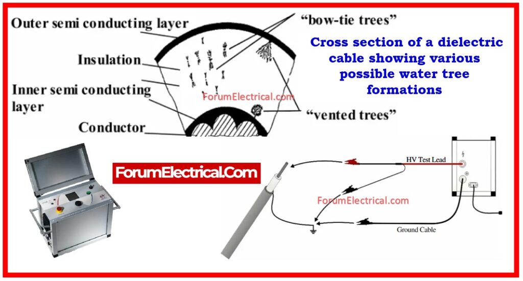
The three most typical reasons of cable failure are
- Water trees,
- Physical damage, and
- Existence of voids.
Finding these at initial stages and finding their location will assist in corrective measures.
Detecting them requires more than just applying a high voltage & measuring the leakage current. More sophisticated measurements are needed, as described below:
- VLF Tan Delta Test
- VLF Partial Discharge Test
- VLF Monitored Withstand Test
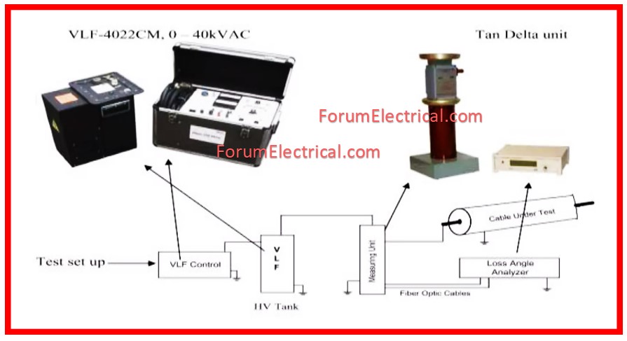
1). VLF Tan Delta Test
Tan delta, more commonly referred as dissipation factor, is a measurement of the currents that flow via insulation when an AC voltage is placed between the cable conductor and ground.
Usually, there will be a low resistive current & a high capacitive current. The tan delta value is calculated using the ratio of these two factors.
The insulation’s state worsens as the tan delta value increases (and fluctuates with voltage).
Tan delta, as measured using a VLF test kit, is extremely susceptible to the water trees & also physical damage.
Furthermore, IEEE 400.2 specifies and regulates the utilization of VLF tan delta.
The IEEE recommends the procedure for both new & aged cables.
2). VLF Partial Discharge Test
Partial discharge (PD) is a phenomenon caused by a partial breakdown of the dielectric, resulting in the transfer of electric charges.
This is most common in voids within insulation caused by manufacturing faults or poor site installation procedures.
This localized breakdown under the application of the high voltage (HV) will result in electrical treeing within insulation and subsequent failure.
PD activity can be detected early on by connecting a particular sensor (capacitive coupler) to the cable & applying a high voltage (HV) VLF signal with IEEE 400.3 as reference.
The greatest advantage of the VLF PD test is that it also indicates the location wherein PD happens so that corrective action might be taken.
3). VLF Monitored Withstand Test
The VLF Monitored Withstand Test is a high-voltage (HV) test that evaluates the insulation integrity of medium-voltage power lines.
It employs Very Low Frequency – 0.1 Hz (or) lower) AC voltage to reduce power consumption while stressing the cable insulation.
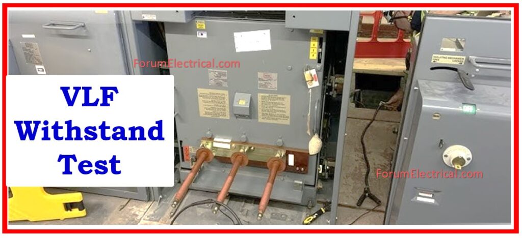
This test combines a withstand test (pass/fail depending on insulation strength) with diagnostic data like tan delta and partial discharge measurements.
It assists in the detection of
- Insulation age,
- Moisture infiltration, and
- Internal faults
prior to cable energization.
It is commonly used according to standards such as IEEE 400.2, particularly after cable installation (or) repair.
Why 0.1 Hz?
When testing a load with AC high voltage, lower frequencies result in lower current and power requirements.
A VLF AC hipot is the easiest and cheapest way to test AC (alternating current) high voltage field loads with substantial capacitance, including cables and motors/generators.
The usual frequency for the VLF testing has long been: 0.1 Hz. Most VLF instruments can produce output frequencies ranging from 0.1 Hz to 0.01 Hz, which is permitted by international standards.
For cable testing, 0.1 Hz to 0.01 Hz is permissible, however 0.1 Hz and 0.05 Hz are preferred. Motor & generator coil testing needs 0.1 Hz. For other VLF testing, as detailed subsequently, 0.1 Hz is required.
Advantages of VLF Testing
- VLF testing detects possible problems before they cause catastrophic failures, enabling proactive maintenance.
- VLF cable testing can predict future cable problems. Engineers can detect cable properties and forecast failure by testing it over time. This lets maintenance arrange repairs prior to the cable failing, decreasing downtime and costs.
- This test does not harm the device being tested.
- Cable failures can endanger people and equipment. VLF cable testing reduces electrical accidents & equipment damage by finding cable problems early and repairing them.
- VLF test equipment is frequently portable, which makes it simpler to conduct testing in the field.
- VLF testing helps minimize costly outages and replacement expenses by identifying cable faults early and maintaining them.
Application of VLF Testing
- VLF testing has two main applications: AC field testing of medium and high voltage cables, and testing of rotating machinery such as motors and generator coils.
- Several international standards specify and sanction these two applications.
- IEEE 400.2-2013 is for cable testing, while
- IEEE 433-2012 is for rotating machinery testing.
- VLF can be used to test high capacitance loads such as insulators, arrestors, and bus ducts, however there are no accepted standards.
- VLF is effective for assessing cable and accessory installation quality, including splices and terminations.
- Cable breakage, incorrect installation, and faulty materials are common causes of service failures.
- VLF acceptance testing following installation and repair of cable faults helps prevent in-service failures.
- To test motor and generator coils, manufacturers must use 50/60 Hz. power frequency AC Dielectric test sets, often known as hipots.
- VLF is ideal for rewind and repair shops, as well as field maintenance testing, due to its size, weight, and cost-effectiveness compared to huge, heavy, and difficult-to-set-up 50/60 Hz. hipots.


