
What are Variable Speed Drives (VSD)?
A variable speed drive is an electronic device used in electrical as well as mechanical driving systems which enables the user to easily control the speed of an AC motor.
- What are Variable Speed Drives (VSD)?
- Purpose of Variable Speed Drives
- How does a Variable Speed Drive Work?
- Purpose of Commissioning VSD
- Choosing the Appropriate Application Settings
- Choosing the Right Parameter Settings
- Types of Variable Speed Drives (VSD)
- 1). DC Motor Drives
- 2). Eddy Current Motor Drives
- 3). AC Motor Drives
- Difference Between Variable Speed Drive (VSD) and Variable Frequency Drive (VFD)
- Variable Speed Drive vs Variable Frequency Drive (VSD vs VFD)
- Advantages of a Variable Speed Drive (VSD)
- Disadvantages of a Variable Speed Drive (VSD)
- Application of a Variable Speed Drive (VSD)
They also include helping in the monitoring of the generated torque through adjusting the input speed as well as voltage of the motor.
Variable speed drives can also control the flow of the motor continuously and it is very accurate. They are mainly designed to serve industrial needs for the regulation of the revolution rate of the coupled motor system.
These drives alter the speed that is applied to a motor by variation of the input voltage and are suitable for both,
- AC motors and
- DC motors.
Variable speed drives get particular amperes and volts to a motor. When the supply power is AC, VSDs use a rectifier circuit to convert the AC to DC at a voltage and amperage that is controlled by the drive.
This means that whenever the voltage of the DC is altered, the speed of the motor will also be altered. A DC motor VSD can be of very simple circuit and thus are generally cheaper than VSDs, therefore very economical.
Variable speed drives are also incorporated in large fans, air conditioners, industrial fillers and so on. Most of the variable speed drives contain an electric motor as well as a controller which is used for controlling the speed of the motor.
In addition to variable speed drives, motor speed governor is also employed here with the help of which maximum speed reachable by the motor at a given time is controlled. This helps to avoid the motor from reaching its high rpm levels, which are sufficient enough to damage it.
Purpose of Variable Speed Drives
Electrical motors are among the most essential components that are used in daily operations, and they are present in almost all appliances used in our day-to-day activities.
These motors should be supplied with an electrical input line in order for it to function and develop torque and speed proportional to the amount of energy that is used.
But to maintain them for increased and extended motor functions, additional energy input is required and if not sufficient, the motor could only perform sub optimally with more energy wastage.
Variable speed drives can conveniently be fitted on electrical motors where speed or torque-relation of the motor is needed in relation to the load.
Therefore variable speed drive is easily fitted to AC motors as being an integral part that enhances the motor enormously.
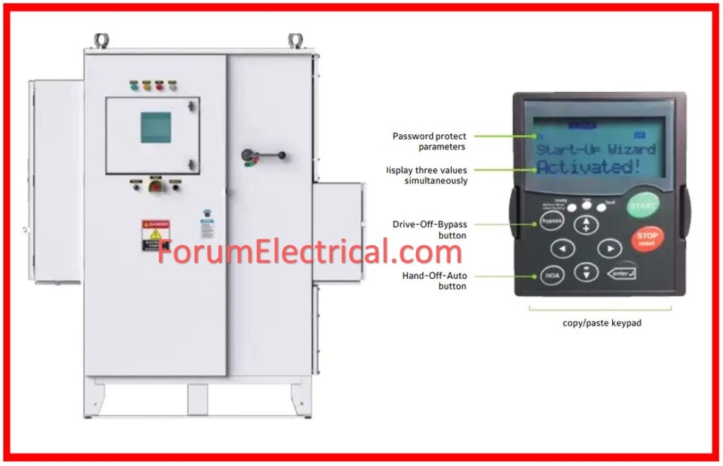
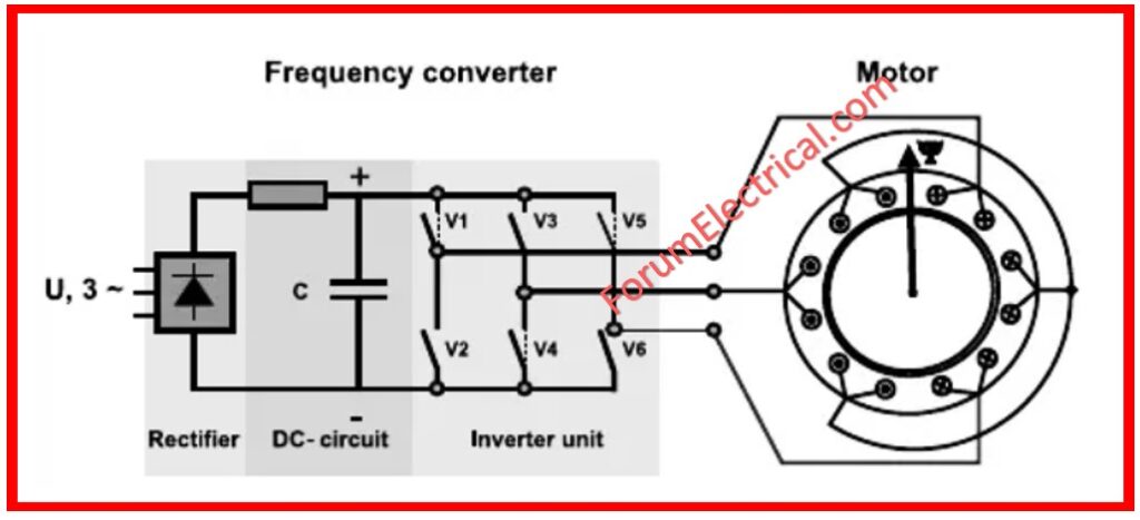
How does a Variable Speed Drive Work?
An AC variable speed drive is also referred to as an AC drive or a variable frequency drive (VFD) or an Inverter. This is a device that can be utilized in order to regulate the speed of an AC motor. The fundamental purpose of an AC variable speed drive is to rectify the incoming AC voltage into DC voltage, and then reconvert it into AC voltage of variable frequency and voltage.
Below are the components of an AC variable speed drive and details on how they function:
Rectifier: A rectifier lies directly before the inverters in an AC variable speed drive and is responsible for the conversion of the received AC voltage into direct voltage; the rectifiers are usually either a diode or thyristor based.
DC Circuit: The DC circuit is actually a capacitor bank that acts to filter the DC voltage, and supplies a constant voltage to the inverter section.
VSD: The next component is the inverter which is the chief part of the AC variable speed drive; it is the function of the inverter to take the DC voltage from the DC circuit to produce AC voltage with varying frequency and voltage level. In the inverter occasion, the DC voltage is switched at high frequencies utilizing insulated bipolar transistors (IGBT’s).
Control Circuit: The control circuit enables it to control the speed of the motor and the output voltage of the inverter control circuit of the motor and it can be either open loop, closed loop or vector control in accordance to the respective application involved.
In general, the AC variable speed drive makes it possible to vary the motor speed in response to the frequency and voltage of the AC output.
It is then possible to control the energy which the motor consumes and other benefits of using this method of motor control would be the reduction in the wear and tear of the motor as well as that mechanical driven application which is connected to it will enhance the efficiency of the whole system.
Purpose of Commissioning VSD
The main purpose of commissioning VSDs is to ensure that:
- The AC converter and the motor will be wired and installed accurately and will conform to wiring and safety standards as discussed in IEC 60364 (or) the Australian standard AS 3000.
- The power and motor cables are the correct size, properly placed and properly terminated as well.
- All the power cable shields have been well connected to earth at both ends as at the converter terminal and the motor terminal and at the DB or MCC.
- The control cables have been also installed in accordance with the design of the control system.
- Correct earthing of control cable shields has been provided at one end only at the ‘cleaner end’ of the process control system.
- Conducting the energization for the first time, there is no fault that emanates from the cables.
Choosing the Appropriate Application Settings
This is done after all the primary assessment tests have been run and the commissioning test sheet filled in and the VSD is now ready to be energized.
When the energizing of the converter has been done for the first time it is advisable that the motor cables should be disconnected until all the basic parameters settings have been programmed into the converter.
This will help to prevent such issues as when the motor is started in the wrong direction, when its acceleration time is too high, etc.
However, there is no harm in running a PWM converter with the output side left open circuit.
If all the basic settings and the on-load tests have been carried out then the motor cable may be insulation tested and finally connected for the on-load commissioning tests.
Choosing the Right Parameter Settings
Variable speed drive will only work efficiently if the basic parameters have been properly set to the particular application.
The following basic characteristics must be verified before connecting the VSD to a mechanical load:
The correct base voltage has to be chosen for the supply voltage and also for the electric motor which has been connected to the output. This will guarantee that a right volts/Hz ratio is displayed to the motor and to sustain the inbuilt electric motors quality.
The correct base frequency must be selected in respect of the supply voltage and according to the electric motor to be driven at the output side. The standard frequency is usually 50 Hz. This will ensure that the right volts/Hz ratio output is given to the motor.
The connections to the cooling fan should be checked to see whether the correct tap on the transformer has been chosen.
Following that, select the remaining parameters:
- Maximum Speed
- Minimum Speed
- Motor Rotor Current
- Current Limit
- Acceleration Time
- Deceleration Time
- Starting Torque Boost
Maximum Speed
Synchronous speed, typically 50 Hz, although the speed is sometimes adjusted to a higher value depending on the intended use of the motor. It is also important to make sure that the speed is not pushed to the maximum limit of load ability for the drive.
Minimum Speed
Slip, generally set at 0 Hz for a pump or a fan drive but can be set at a higher value to suit constant torque loads. Be very careful that the minimum speed does not take the drive below the load ability limit.
Motor Rotor Current
Only the rated current of the motor should be drawn from the supply in order to avoid engaging over-current protection.
Stator current rating of the motor which depends on the size of the motor in relation to rating of the converter. The current rating of the converter has to be always equal to or greater than the motor rating at any time. In order to afford the right amount of protection to the motor, the right current rating should be selected.
Current Limit
Present limit decides the no- load or initial torque of the motor. Holding values up to 150% provide the maximum starting torque if a high breakaway torque is expected.
Acceleration Time
Acceleration time defines the time needed for the increase of the speed from 0 to its maximum value. It should be selected in a way proportional to the mechanical load inertia and the type of their usage.
Deceleration Time
Deceleration time which controls the time taken to slow down to zero from the maximum speed. This setting is only if the ‘ramp to stop’ option is used. Other options are invariably ‘coast to stop’ and ‘DC braking’.
NOTE: On high inertia loads, which in general are loads with large moments of inertia, it should not be set too short. If the time taken for deceleration is less than the inherent rundown time of the load, then the DC voltage will build up to a very high level and cause tripping on ‘over-voltage’.
It is limited to being shorter than natural rundown time using a dynamic braking resistor.
Starting Torque Boost
Starting torque boost can be selected if the load has high breakaway torque. It is useful for this purpose but should be utilized with a lot of care so as not to over-flux the motor at lower speeds. Setting at this level has the risk of overheating the motors.
Sufficient torque boost only should be chosen to make the VSD go beyond the breakaway torque of the load at start-up.
The previously mentioned factors are essential and must be verified initially.
Most of the other parameters will have a ‘default’ value and this will likely be sufficient for most applications. However these should be checked and adjusted for their optimum performance level.
Types of Variable Speed Drives (VSD)
There are several variable speed drives as listed below:
Three general types of variable speed drive are
- DC Motor drives,
- Eddy Current Drives and
- AC Motor drives.
Variable speed drives can be classified under certain categories and each category can have more subcategories.
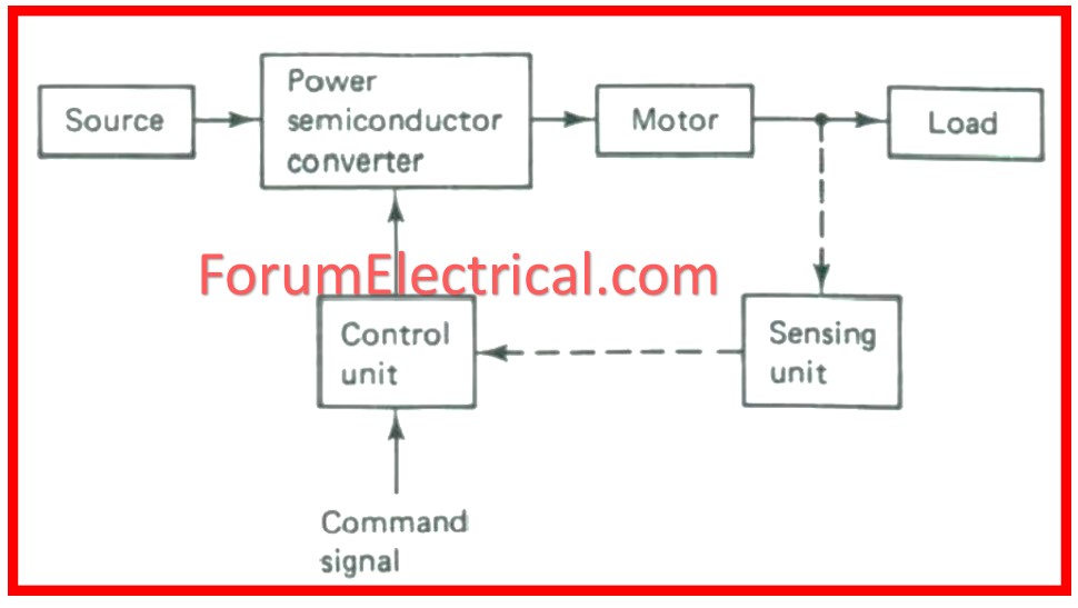
All variable speed drive systems will consist of an electric motor and a speed control device.
Variable speed drive technology presently is made of electronic components in circuit systems and are solid-state devices.
In the older systems of variable speed drives, mechanical components were used that sometimes fail as they have moving and worn out parts.
1). DC Motor Drives
DC drives are also called DC Motor Speed Control Systems.
A DC motor can have its speed vary as the armature voltage hence this can be manipulated to control the motor speed and also varies inversely with motor flux, so either armature voltage or field current can be used to control the motor speed.
AC Motors are no longer costly and thus today many dc motor speed control systems have been replaced by an AC motor and AC variable speed drive.
AC variable speed drives are cheaper than DC systems, are more obtainable and are more effective than DC systems.
2). Eddy Current Motor Drives
An eddy current drive is made of a fixed speed motor and an eddy current clutch.
It has a fixed-speed rotor and an adjust- able-speed rotor situated in the same space but with a very narrow air clearance between them.
A direct current in a field coil creates a field that defines the torque from the input to the output rotor.
The controller gives a closed loop speed control by changing the clutch current hence enabling the clutch to transmit adequate amounts of torque to enable the motor to work at the desirable speeds.
The shifting is facilitated by an integral AC tachometer, for speed feedback.
Eddy current drives have the least efficiency compared to other types of drives. Most of the eddy current motor drive systems are currently considered to be outdated.
Currently there are very few manufacturing facilities that still apply eddy current motor drive systems in their operations, when the equipment breaks down it is costly to repair and in most cases it is virtually impossible to purchase new ones.
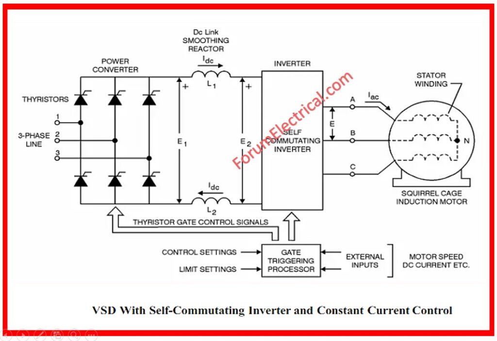
3). AC Motor Drives
AC variable speed drives are also referred to VSDs, variable frequency drives, VFDs, inverters, adjustable speed drives and micro drives.
AC variable frequency drives are applied in numerous equipment including swimming pool pumps, air compressors, conveyor systems, turning-milling machine tools, food processing product line system, waste water treatment pump system, HVAC fans and blower system and hundreds of other OEMs in the wide range of manufacturing industry.
Over 30% of global electrical-energy consumption is used by electric motors in constant-speed centrifugal pump, fan and air compressor lines.
This shows that much can be gained by the industrial manufacturing world in terms of energy efficiency improvement, if older DC motor speed control systems and eddy current drive systems are upgraded with AC variable frequency drive systems.
Difference Between Variable Speed Drive (VSD) and Variable Frequency Drive (VFD)
Variable Speed Drive vs Variable Frequency Drive (VSD vs VFD)
| Parameters | Variable Speed Drive (VSD) | Variable Frequency Drive (VFD) |
| Definition | A device that regulates the speed of equipment by the use of one method or another. | A specific variety of VSDs that control the speed of the motor by changing the supply voltage frequency. |
| Method of Speed Control | Can be with mechanical drive, with electrical drive or hydraulic drive. | It uses electrical frequency variation with a view of controlling the speed of the motor. |
| Application | Broad category which encompasses various methods of controlling speed. | Designated for use on alternating current motors particularly those of industrial use. |
| Common Usage | Inclusive terminology that also refers to VFDs and other approaches to speed regulation. | Used in industries especially for accurate speed of motor regulation. |
| Technology | It may consist of variable pitch drives, variable diameter pulleys and other parts. | This is accomplished primarily through power electronics and digital controllers. |
| Energy Efficiency | It can be either Low or High depending on the technology used. | Energy-saving in most cases because of high control. |
| Complexity | It can be of simple form or complex depending on the particular technique that is used. | Usually, these are more complicated which include the use of more electronics. |
| Cost | It greatly differs depending on the type that is used and the area of use. | The initial cost is usually higher but outweighs the energy cost in the long run. |
| Maintenance | It usually depends on the type of building; more often mechanical systems may need frequent maintenance. | They are generally less demanding in terms of maintenance, since they have fewer components that can wear out. |
| Examples | A hydraulic drive, a mechanical drive, and a VFD. | Heating, ventilation and air conditioning equipment motors, conveyors, and pumps with AC motor controllers. |
Advantages of a Variable Speed Drive (VSD)
- Variable speed drives are used extensively to regulate the speed of various ac motors used in industrial and commercial applications. It makes easy applications such as flow, acceleration, speed, pressure, temperature, torque, tension and monitoring.
- They are also exposed to higher torques that result in more energy consumption than variable speed loads and also take the motor through mechanical and electrical stress. When the motor is made to move in a specific manner for instance the S-curve pattern, the variable speed drive is able to equate mechanical and electrical stress. It also helps in the regulation of smooth deceleration and acceleration control.
- As the variable speed drives provide some measure of protection from mechanical stress and ensure that the motor is safeguarded from dangers during the frequent speeding up and slowing down changes, it adds to the overall longevity of the motor. Additionally, it decreases the frequency of maintenance, and compromises on extremely high repair expenses.
- In auxiliary, one of the key positive impacts of applying a variable speed drive is energy-saving options. Fixed speed loads employ traditionally much larger current to operate, this can subject the motor to electrical stress.
- However, the energy consumption can be reduced significantly using VSDs Variable speed drive: A device used to control the speed of an AC motor using variable frequency. For this the motor application that is connected with the main power line is operated with a variable speed drive. Variable speed drives therefore reduce energy consumption by a wider margin than fixed speed loads.
Disadvantages of a Variable Speed Drive (VSD)
- Variable speed drives come with several concerns in businesses, the most concerning being the initial cost. The conversion to VSDs involves appreciable amounts of money to be spent on equipment and their installation. However, despite the ability to generate considerable energy savings in the long term, some organizations can struggle to justify the initial outlay for VSDs. Meanwhile, these drives offer significant gains in the long term since they lead to optimization of energy usage and decrease in operational expenses.
- VSDs required a professional hand for the installation and for the regular maintenance work. Their integration into existing systems may present some problems to enterprises which do not possess such knowledge or are small or new. Maintenance is one aspect that is seriously vital for the performance, and cases of lack of it are synonymous for decreased performance or a nonworking drive.
- Harmonics can be created due to the ‘switching’ action involved in the use of variable speed drives. These harmonics can cause disturbances and affect the overall power quality of the system. Harmonic distortion can at times affect other equipment in the same power network adversely, resulting in equipment malfunction, early failure, increased maintenance cost etc. Reducing harmonics implies the use of accessories like harmonic filters and these all result in increased cost and complexity in the system.
- Motors driven by VSDs at lower speeds can be cooled insufficiently which can result in motor overheating. With the motor, it is paramount to think how it should be cooled, and if it is to be cooled, whether there are proper provisions for this cooling. Selecting the correct motor, protecting the electrical motor from heat and monitoring it frequently can save many customers from frequent problems of overheating.
Application of a Variable Speed Drive (VSD)
- Crane and Hoist Machines: Variable speed drives are incorporated in asynchronous motors in hoist equipment and also cranes. It assists in realizing close to an optimum of 90% degree of effectiveness when it comes to the lifting of weights.
- Treadmill: VSDs are applied together with an AC motor in treadmills to ensure that the power can be delivered easily in cases of frequent and rapid changes in torque. Therefore, they have replaced DC motors of old generation and offer improved protection of stator windings from thermal damage.
- Air-Conditioners: This is the most common use of the variable-speed drive as it is its most obvious use. Specifically, VSDs in ACs assist in controlling the temperature. Further, they are also seen to contribute a great deal to acts of environmental conservation that include reduction of carbon emissions and saving on energy consumption.
- Thermal Power Plant: Asynchronous motors are used constantly in thermal power plants. Medium voltage VSDs or VFDs are employed for reorganizing the water supply pumps for higher control and minimum consumption. VSDs change the speed of the motor depending on the water that is needed for the functioning of the equipment. They achieve this by regulating energy expenditure.
- Oil Industry: Most of the oil industry uses speed motor drives when pumping the oils. The use of VSDs has assisted this industry in addressing the power consumption problems that are a function of load size. They also enable high frequency range, the degree of exactness of performance, and the dynamic reaction.
- Irrigation: The application of variable speed drives on irrigation pumping bring in the reduction of cost. They are normally applied to a motor in reference to the curve of the irrigation pump.


, from initial setup & parameter design to testing and final adjustments, to ensure your system's best performance and energy efficiency.)