
What is an Electrical Connector?
Electrical circuits are made up of several different components, including
- Cables and
- Wires.
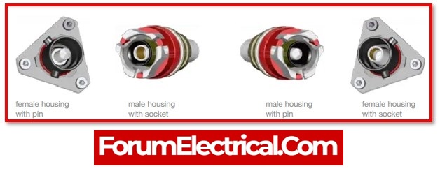
Electrical connectors are utilised to connect these in order to provide a continuous conduit for electrical power to flow. Connectors feature male and female ends (plugs and jacks) that join to make either a permanent or temporary connection that may be assembled and disassembled with certain equipment. Electrical connections significantly minimise the time, effort, and professionals required for the manufacture, assembly, and installation of electrical devices, their components, and wire.
Connectors make it possible for
- Wires,
- Cables,
- Printed circuit boards, and
- Other electronic components
to make contact with one another.
They also make circuit repairs easier and provide for more design and modification flexibility. They are widely utilised in
- Communications,
- Computer,
- Industrial equipment, and
- Consumer electronics circuits.
Components of Electrical Connectors
Most connectors are made up of major components:
1). Housing
2). Terminal
3). Contact
4). Shell
5). Eyelet
1). Housing
Housing is the casing or framework that holds the terminals, stabilises the connection, and protects the contacts from the shorting &/or other environmental dangers. Housing is often constructed of moulded plastic, however it may be designed of any kind of insulator material (for example, ceramics).
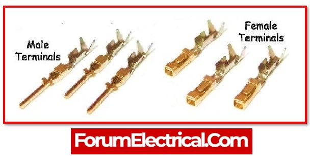
2). Terminal
Terminal pins inside the connector are responsible for providing the conductivity of electricity that is necessary to make the connection. They are mostly typically constructed of metal, however any material that transmits electricity (for example, carbon or silicon) may be utilised.
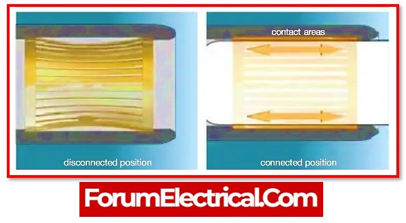
3). Contact
When connectors are joined together, a contact for establishing an electrical connection between the two devices is established.
4). Shell
A protective shell that encloses both the insulator & the contact.
5). Eyelet
Connective element that holds the housing & the shell together.
Electrical Connector Types
There are several separate electrical connectors types that may be distinguished in a variety of ways, including
- Level,
- Function or Type, and
- Termination.
Connector Level
Each connection type may be classified into one (or more) of five levels in the industry.
1). Wire-to-board (or) subassembly-to-subassembly level
2). Box-to-box (or) input/output level
3). IC chip (or) chip-to-package level
4). IC package (or) package-to-board level
5). PC board-to-board level
Connector Types
1). Audio and Video Connectors
2). Automotive Electrical Connectors
3). Board Mount Connectors
4). Board to Board Connectors
5). Centronics Connectors
6). Circular Connectors
7). Coaxial Connectors
8). DIN Connectors
9). D-Sub miniature Connectors
10). Edge Connectors
11). Fiber Channel Connectors
12). FireWire Connectors
13). Gender Changers
14).Heavy Duty Rectangular Connectors
15). IC Interconnect Components
16). Instrument and Computer Power Connectors
17). Medical Electronic Connectors
18). Micro Connectors and Nano Connectors
19). Military connectors (MIL-SPEC)
20). RJ Connectors and Modular Connectors
21). Panel Interface Connectors
22). PC Card Connectors
23). Phone Jacks and Plugs
24). RF and Microwave Connectors
25). Solar Connectors
26). Solenoid Valve Connectors
27). Terminal Blocks
28). Thermocouple Connectors
29). USB Connectors
30). Wire Terminals
31). Wire to Board Connectors
32). Wire to Wire Connectors
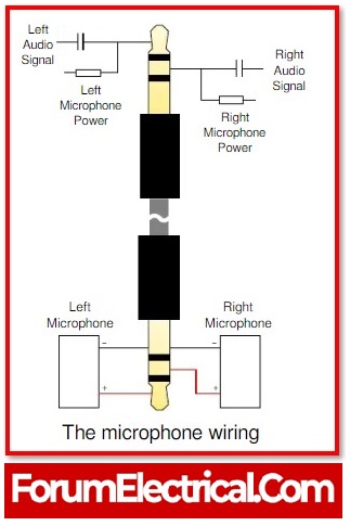
1). Audio and Video Connectors
Audio connectors enable wires to connect to other audio equipment and protect grounding. Audio connections may be used for a variety of purposes, including general purpose, telephone, and microphone applications. The majority of audio connections are for commercial use, however some may meet military criteria.
2). Automotive Electrical Connectors
Automotive electrical connections are designed particularly for use in automobiles.
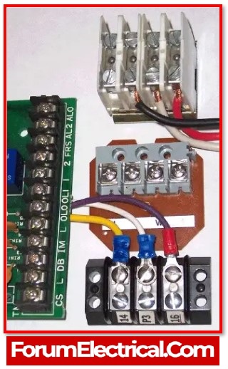
3). Board Mount Connectors
Board Mounted Connectors, also known as Circuit Board Connectors, typically consist of connectors that can be utilised as integrated components on the computer’s motherboard board.
4). Board to Board Connectors
Board to board connectors that are able to be employed as parts on a computing board & the boards are able to be customised to match the requirements of the user application.
5). Centronics Connectors
Centronics connections are common parallel interface devices used to connect printers and other peripherals to computers, such as
- Portable disc drives,
- Tape backup drives, &
- CD-ROM players.
Centronics connections are named after the first printer to utilise them and have two rows of flat contacts.
6). Circular Connectors
Circular connections are multi-pin connectors designed mainly for external interfacing. They may be used to
- Convey data,
- Transmit electrical signals, or
- Power electrical equipment.
In specific conditions, circular connections have been developed to handle a mixed signal and are referred to as power and control connectors. These multi-pin connectors are used to transmit both power and signals.
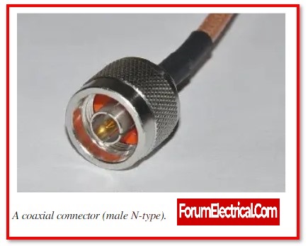
7). Coaxial Connectors
Coaxial connections are made out of an insulated central conductor that is encased in another cylindrical conductor (the shield). Another insulating layer & an outer protective layer are frequently wrapped around the cable. Coaxial connectors and coaxial cables have the ability to transfer large amounts of data. They are often utilised in high-speed data transmission and Community Antenna Television (CATV) applications.
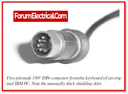
8). DIN Connectors
DIN connectors are multi-pin, high-frequency electrical connectors. DIN connections have circular, notched ends that are shielded by a metal skirt that makes sure that pins line up properly.
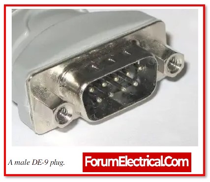
9). D-Sub miniature Connectors
D-sub miniature connectors, more often referred to as D-sub connectors, are the robust electrical connectors that have a mating face shaped like the letter D. Because male & female connectors can only fit together in one direction, they offer polarisation.
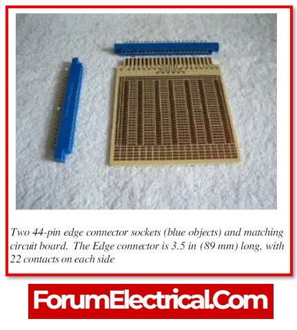
10). Edge Connectors
Card edge connectors are embedded devices that match with edges of single-sidedprinted circuit boards (PCBs) (or) double-sided printed circuit boards (PCBs) to provide an external electrical connection. Power standards like as
- Voltage levels,
- Power pin locations, and
- Power requirements
are defined by industry standards.
Power parameters for peripheral component interconnect (PCI) and industry standard architecture (ISA) buses, for example, are defined by PICMG 1.0/1.2 standards.
11). Fiber Channel Connectors
High-speed connections used in Fibre Channel systems are known as Fibre Channel connectors.
12). FireWire Connectors
FireWire equipment such as
- Host controllers,
- Adapters,
- Hard drives,
- Hubs,
- Repeaters, and
- Card readers
are connected using IEEE 1394 connections. FireWire, a registered brand of Apple Computer, is a communications technology that allows data, video, and audio to be sent at very high bit rates over a single connection.
13). Gender Changers
Devices known as gender changers are able to turn the end of the cable into a new type. This makes it possible for two cable assemblies with the same (or different) genders to mate.
14). Heavy Duty Rectangular Connectors
Heavy duty rectangular connectors are designed to withstand significant electrical loads & direct signals in a range of different operating conditions. These connectors may also be used in a variety of different applications.They are often employed in industrial applications where significant power is needed. As a result, specific terminations such as
- Solder cup,
- Wire wrap, and
- Other high duty terminals
are employed to ensure safe power transmission.
15). IC Interconnect Components
Through the use of an integrated circuit connection interface, microelectronic semiconductor chips may be connected to larger-scale devices such as printed circuit boards (PCB). An electrical interconnect device connects two conductors and enables current (or) light waves to pass from one to the other.
An integrated circuit (IC) on the silicon (or) metal die is housed in a
- Ceramic,
- Plastic, (or)
- Metal enclosure
in electronic packaging.
16). Instrument and Computer Power Connectors
Computer (disc drive) and instrument power connections Power connections link the power supply of a computer to a
- Hard disc,
- Floppy disc,
- Compact disc (CD),
- Digital video disc (DVD), or
- Other form of disc drive.
They are also utilised with the removable media drives like Zip discs, as well as computer cooling equipment like fans & electro-thermal coolers.
17). Medical Electronic Connectors
Medical electronics connections are used in hospitals, clinics, physicians’ offices, & other health-care institutions with medical devices and equipment.
18). Micro Connectors and Nano Connectors
Micro and nano connectors have contact pitches of 0.05″ (micro) & 0.025″ (nano), accordingly.
They are either straight or right-angled and feature one (or) more rows of plated contacts. Some micro and nano connections are round or cylindrical in shape. Others are intended for coaxial cables, as well as RF & microwave applications.
There are both male & female equipments available. Micro and nano connectors are utilised in a wide range of industries & applications.
19). Military connectors (MIL-SPEC)
Military (MIL-SPEC) connectors are the shell-type connections designed to meet military requirements. Because they are designed to secure the connection from environmental variables, they may be employed in military & aerospace applications.
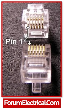
20). RJ Connectors and Modular Connectors
Modular connectors and RJ connectors are two types of connectors that are similar yet unique.
Modular connectors are made up of “plug-in units” that may be combined to increase the size of the system, enhance its capabilities, or extend its size.
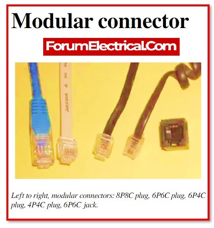
Registered Jack (RJ) is an FCC-registered telephone & data jack application specific connection.
21). Panel Interface Connectors
PICs are devices that are positioned on the exterior of a panel that holds a PLC, a computer, (or) other devices. The PIC enables the operator to connect with the PLC or computer without having to open the panel door, hence eliminating possible safety issues. Power outlets and communication ports may be combined in a variety of ways to create a wide range of customisable devices.
22). PC Card Connectors
PC card connections are used to connect computers to CompactFlash cards, PC cards, & other devices.
The
PCMCIA – Personal Computer Memory Card International Association
a trade organisation for the computer industry in the United States, defines and maintains the PC card form factor. PC cards, initially known as PCMCIA or PCMCIA cards, were developed for computer storage expansions. They may now be found in
- Network cards,
- Modems, &
- Even hard discs.
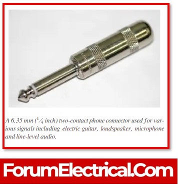
23). Phone Jacks and Plugs
Phone jacks & plugs are telephone connections. Modular jacks (female) & modular plugs (male) are other names for them.
24). RF and Microwave Connectors
Connectors that work with radio frequencies (RF) and microwaves are used to connect the two ends of cables that are used in radio frequency or microwave systems.
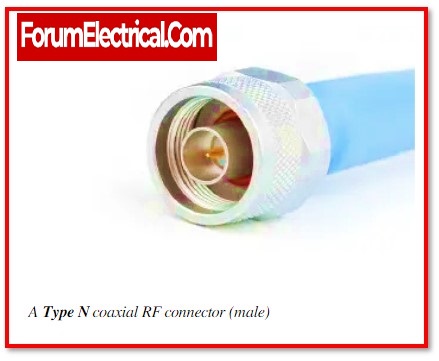
Microwave energy is electromagnetic energy with the frequency more than one gigahertz and a wavelength less than 30 cms.
When an alternating current is sent into an antenna, it produces an electromagnetic field ideal for the wireless broadcasting (and/or) communications.
An RF connection is utilised in gearbox systems and permits system components to be coupled or uncoupled. A mated pair is made up of a plug & a jack.
25). Solar Connectors
Solar connectors make electrical connections in the solar energy systems possible. The solar enterprises employs several variations of connectors or conventional non-connector junction boxes, which are the key distinguishing features of solar modules.
26). Solenoid Valve Connectors
Solenoid valve connections join solenoid valves & pressure switches. As environment resistant junction boxes, solenoid valve connections are often utilised. These enclosures are suitable for use with hydraulic (or) pneumatic solenoid valves (or) pressure switches. Specific equipment can operate with either AC (or) DC voltages, however some can manage both.
27). Terminal Blocks
Terminal blocks are insulated, modular blocks that connect two or more wires.
Terminal blocks are utilised to fasten (and/or) terminate wires & are made up of multiple separate terminals grouped in a long strip in their most basic form.
Terminals are used to link wire to a ground (or) in the case of electrical power, to connect electrical switches and outlets to the power supply.
28). Thermocouple Connectors
Thermocouple connections are utilised to transmit thermocouple (T/C) temperature data.
These specialised connections are intended for extending the thermocouple wire & must be T/C rated.
The lettered thermocouple various types consist of B, C, E, J, K, N, R, S, T, & W.
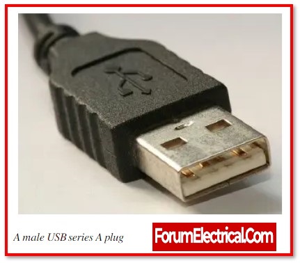
29). USB Connectors
USB connections are used in conjunction with USB ports. They may be utilised for connecting USB devices as well as USB cables & peripherals to other common port types.
30). Wire Terminals
Wire terminals comprise passive conductors intended to permit a non-soldered connection. They consist of two-piece assemblies made up of a receptor (female) & a blade (male) which helps in repetitive attachment and dissociation. There are several product types.
- Spade terminals,
- Ring terminals,
- Blade terminals, and
- Heat-sinkable terminals are among examples.
31). Wire to Board Connectors
Wire-to-board connections employ connectors linked to wires to connect printed circuit boards (PCBs).
32). Wire to Wire Connectors
In order to connect the two wire-terminated connections, wire-to-wire connectors are utilised.
- Electrical connectors,
- Electronic connectors, &
- Computer connectors
are all examples of connectors.
The primary specifications of a wire-to-wire connectors are
- The mating combination (also known as gender),
- The number of circuits (also known as locations), and
- The wire size.
Connector Termination
Some connectors can be further classified depending upon how the wire is connected to the connection, they are
1). Crimping
2). Insulation Displacement
3). Soldering
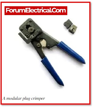
1). Crimping
Crimping is a method of making a detachable connection between wires & connections. It entails placing a stripped wire into a metal piece (barrel or termination) and applying pressure to compress the portion firmly around the wire using a crimping tool. They are frequently utilised to terminate stranded wire. Crimping is used to attach a wire to a ring, spade, or blade connection.
Crimped connections are frequently desired for a variety of reasons, including:
- Connections are simple, quick, and inexpensive to make/reproduce in large-scale manufacturing, and there are no risky procedures required.
- The connection has less mechanical strain.
Crimped connections come in two varieties:
- Barrel Crimped Connection and
- Open-Barrel Crimped Connection.
a). Barrel Crimped Connection
Crimping cylindrical portions into an oval-like form (depending upon the tool) is required for barrel connections. These are often utilised in everyday consumer applications.
b). Open-Barrel Crimped Connection
Crimping a pre-crimp segment into a U or V shape is required for open-barrel connections. These connections are more popular in industrial applications since they are simpler to automate and typically stronger than the barrel crimped connections.
2). Insulation Displacement
Insulation displacement connectors (IDCs) are employed for connecting an insulated wire or cable to a device without the cable or wire being pre-stripped.
The insulation is sliced as it is placed into the connection by integrating a sharp blade (or) numerous blades.
IDC connections are ideal for manufacturers since they remove the need for stripping, resulting in a simpler joining procedure.
However, the blade that cut the insulation might sever wires inside the connection over time, reducing current handling (which may lead to connector burnout).
Furthermore, the connection strength is substantially lower than that of a crimped connection. Non-production insulation displacement tools are often more expensive than effective crimping tools.
3). Soldering
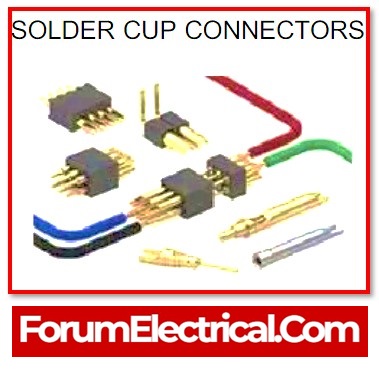
Soldering is the process of melting a filler metal (solder) over an electrical junction. The solder then hardens, resulting in a fusion of two metal components.
If done correctly and with the proper solder (solder components must match the metals of the electrical components being linked), solder may make a highly smooth, durable, and dependable connection. These connections are slower and more complicated than crimped connections.
Electrical connections are formed by soldering wires (or) pins upon a printed circuit board in PCB solder (or) solder pin termination.
Soldering the connector upon the mounting point provides an electrical connection with solder cup terminations.
THT – Through Hole Technology installs components on PCBs by introducing component leads into the board & then soldering the pins on the other side.