
- What is an electrical diagram?
- Electrical Diagram in series
- The Laws of Series Connected Electrical Diagram
- Potential Difference in a Series Connected Electrical Circuit
- Specific features of a circuit connected in series
- Voltage of a Circuit using Series Connection
- Current of a Circuit using Series Connection
What is an electrical diagram?
An electrical diagram is a schematic illustration that shows an electrical circuit (also known as a wiring diagram, electrical diagram, basic diagram, or electronic schematic). A pictorial circuit diagram employs basic representations of components, while a schematic diagram uses standardised symbolic representations to illustrate the circuit’s components and interconnections. The display of circuit component interconnections in the schematic design does not always correlate to the actual arrangements in the actual device.
This electrical diagram is connected in three different forms of connections:
- Series Connection
- Parallel Connection and
- Combined Connection
In this post we can discuss about the electrical diagram in series connection.
Electrical Diagram in series
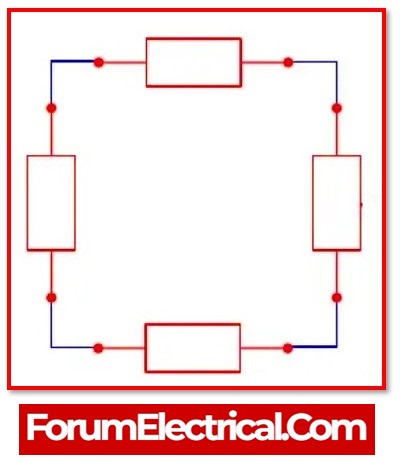
A circuit is said to be series when its resistors are connected in a chain and the current has a particular path it may follow through the circuit. Each resistor receives specifically the same amount of current.The individual resistance values of the resistors in the circuit are added together, and the resulting sum is the overall resistance of the circuit.
Current-coupled circuits or daisy chain-coupled circuits, are different term for series circuits. In a series circuit, the current flows through each and every component that makes up the circuit. Because of this, all of the components that are connected in series carry the same amount of current. In a circuit that is connected in series, there is only one possible path for the current to flow.
Because there is just one path in which a series circuit’s current may flow, opening (or) breaking a series circuit at any point allows the whole circuit to “open” (or) stop working. This can be either a benefit or a drawback, depending on the function that the circuit is intended to perform in the overall design of the device it is supposed to be used.
The Laws of Series Connected Electrical Diagram
Electrical loads (or) resistance that have been connected in series operate in accordance with the principles that regulate series circuits.
Law 1: The overall resistance in the series circuit is equal to the sum of the individual resistances.
Law 2: The flow of current remains unchanged across the entire circuit.
Law 3: Although that the current, measured in amperes, is always the same, there is a decrease in voltage wherever there is a resistance in the circuit.
Potential Difference in a Series Connected Electrical Circuit
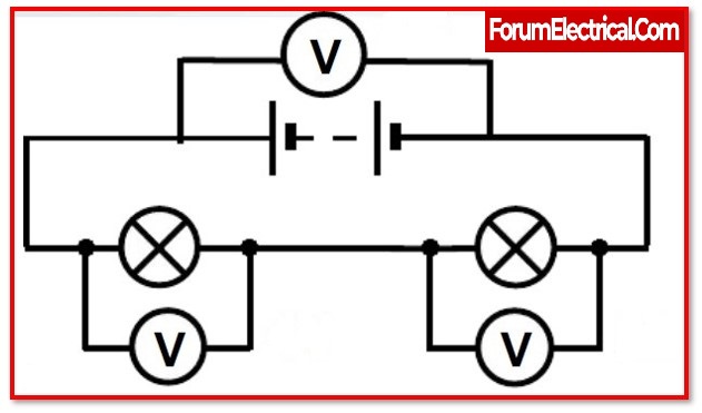
The potential difference across the power supply in a series circuit must be equal to or greater than the potential difference across all of the components in the circuit.The basis for this is that the work done by the battery when it is charging must constantly correspond to the work done by the components. In such condition, there would be a waste of energy. Because of this, the component that has the highest level of resistance will also have the highest potential difference. This is because the charge requires more effort to overcome the higher resistance before it can go through the component. Any change to the resistance of a single component will have a ripple effect on the potential difference between all of the components.
Specific features of a circuit connected in series
- The amount of current that is flowing through each component in a series is the same.
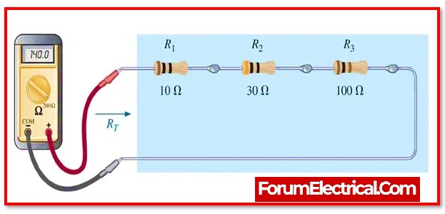
- The total resistance, also known as RT, is equal to the sum of all the individual resistances, which is denoted by the notation
RT=R1+R2+R3
- The total applied voltage (VT) is equal to the sum of the voltage drops that occur across each individual resistance. This is denoted as VRI+VR2+VR3. The name for this theory is Kirchhoff’s Voltage Law. EV’s = 0
- The power generated by each resistor is added simultaneously.
Voltage of a Circuit using Series Connection
The voltage that is measured across a sequence of resistive devices will be proportional to the magnitude of the levels of resistance.
In a resistive electrical circuit arranged in series, the more the resistance, the greater the amount of the applied voltage that the circuit will absorb (that is, the greater the voltage drop across it).
When resistors are connected in series, the ratio of the voltages across them will be the same as the ratio of their resistance levels.
The overall voltage may be calculated by adding together all of the separate voltages.
Calculating across the total voltage of a circuit using series connection as,
The formula for VT is as follows:
VT = V1 + V2 + V3…
(The formula changes depending on the number of the batteries).
Current of a Circuit using Series Connection
The total current flowing through a series circuit is the same as the current that is flowing through each load.
Calculating the total current of a circuit that is connected in series connection as follows:
IT=11= 12 = 13