
What is Breaker Failure Protection?
Breaker Failure Protection (BFP) is a backup protection system that activates when a circuit breaker fails to clear a fault while receiving a trip signal from its protective relay.
- What is Breaker Failure Protection?
- Why Breaker Failure Protection is needed?
- Step-by-Step Procedure of Breaker Failure Protection
- Step-1: Fault Detection
- Step-2: Trip Command & Timer Start
- Step-3: Confirmation Check
- Step-4: Timeout Action
- Step-5: Backup Trip
- Common Components of a BFP Procedure
- Relay Settings
- Main Settings
- Typical BFP Configurations
- Testing & Commissioning
- Factory/Commissioning Tests
- Troubleshooting Common Faults in BFP
- FAQ
If the breaker does not open when it is supposed to receive the trip signal the BFP automatically identifies the failure & trips alternate (or) upstream breakers to isolate the problem from the rest of the system.
Why Breaker Failure Protection is needed?
When a fault (such as a short circuit) happens:
The protective relay detects the problem and transmits a trip signal to the breaker.
Usually the breaker opens and interrupts the fault current.
If the breaker fails to open because of a mechanical (or) electrical failure the fault stays active resulting in:
Serious equipment damage (transformers, generators and switchgear).
Voltage and frequency in the system are unstable.
The malfunction has propagated to other feeders or buses.
Personnel face serious fire (or) safety hazards.
Breaker Failure Protection makes sure that such failures are resolved rapidly by instructing other breakers to open by so protecting the whole system from damage.
Step-by-Step Procedure of Breaker Failure Protection
Step-1: Fault Detection
A protective relay (overcurrent, distance, differential etc.) detects the fault & sends a trip signal to the breaker.
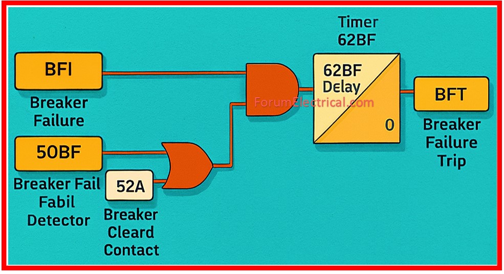
Step-2: Trip Command & Timer Start
Step-3: Confirmation Check
The system utilizes the current sensors (CTs) on circuit breaker poles to determine whether the current has stopped (or) decreased below the predetermined threshold after the projected circuit breaker operation time.
Step-4: Timeout Action
If current remains over the selected threshold after the preset timeout (Eg: 200 ms) the BFP logic determines that the breaker failed to operate.
Step-5: Backup Trip
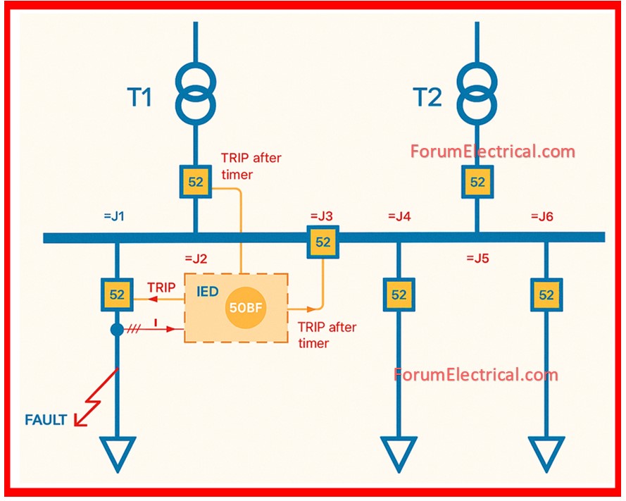
BFP then sends trip commands to pre-selected backup breakers [adjacent feeders, bus tie breakers (or) upstream breakers at the higher voltage levels] to isolate the fault using a different clearing path.
As a result, even if the primary breaker fails to function the fault is quickly cleared by additional breakers ensuring system safety.
Common Components of a BFP Procedure
The protective relay implements overcurrent/differential logic & houses the BFP logic & timer.
- Breaker-Failure Timer
- Current Sensors (CTs)
- Logic/Interposing Circuits
- Trip Outputs to Backup Breakers
- Status & supervision Inputs
Breaker-Failure Timer
The time window within which the breaker must work (adjustable). Frequently included into digital relays.
Current Sensors (CTs)
Evaluate current on the each pole/busbar to determine whether the fault current continues.
Logic/Interposing Circuits
Determine whether the breaker has failed and send backup trip commands; these can be relay logic, interposing relays (or) programmable relay logic.
Trip Outputs to Backup Breakers
Wiring & interlocks for sending trip commands to specific breakers.
Status & supervision Inputs
Status and supervision inputs include breaker open/close status, auxiliary contacts, and trip-circuit supervision for the increased reliability.
Relay Settings
Main Settings
BFP timeout (Tbf)
Typical settings range between 100 and 500 ms, depending on system needs. Many utilities utilize 200-300 milliseconds as their starting point.
Current Threshold
The level below which current can be considered cleared [often a percentage of projected fault current (or) a fixed amperage threshold to prevent incorrect operation during inrush or CT saturation].
Logic Source
Select whether BFP employs breaker auxiliary contact (open detection), CT residual/current monitoring (or) both for confirmation.
Coordination Settings
Ensure that the BFP timeout is longer than the circuit breaker’s mechanical operation time and the relay’s internal processing delay yet short enough to avoid needless fault exposure.
Coordinate backup trips to ensure that upstream (or) nearest breakers that can safely interrupt the fault current while the remaining within their interrupting ratings.
Avoid overlapping BFP zones which could result in more widespread outages than necessary. Use selective tripping wherever feasible.
Typical BFP Configurations
Same-Bay Backup
To clear the fault locally trip the bus coupler (or) adjacent feeder breaker.
Upstream Backup
Trip the upstream breaker on the transformer (or) incoming line.
Breaker Failure with Transfer Trip
If a breaker fails during a transfer trip utilize communication-assisted tripping (e.g: pilot schemes) to order remote breakers as needed.
Testing & Commissioning
Factory/Commissioning Tests
Simulate Failure
Command a trip while manually blocking the breaker (or simulating a failure) and ensure that the BFP timer trips backup breaker.
Primary Injection Test
Inject current to confirm that CT and relay sensing function properly under fault conditions.
Trip-Circuit Supervision Test
Ensure that trip outputs & wiring to backup breakers work as intended and that seals/interlocks are functional.
Routine Maintenance Tests
Periodically check the relay firmware and settings.
Check CT ratios, polarities & health (burden, insulation, saturation tests as needed).
Check the mechanical travel and time of the breaker as well as the auxiliary contacts.
Test trip coils & interposing relays.
Confirm the BFP logic setting in relay firmware.
Confirm the correct CT wiring & polarity.
Check the trip wiring to the backup breakers.
Functional tests include issuing trips, simulating non-operation and observing backup clearing.
Troubleshooting Common Faults in BFP
Nuisance tripping of BFP
BFP nuisance tripping is frequently caused by CT saturation/inappropriate threshold, incorrect time settings (or) error in detection of inrush currents.
Solution: Adjust the threshold, improve CT accuracy (or) change the BFP logic to include auxiliary contact confirmation.
Always synchronize the BFP operation time (Tbf) with the breaker’s rated operating time (IEC 62271-100 or IEEE C37 series).
Failure to Trip on BFP Timeout
Possible causes include a wiring problem to the backup breaker, a defective trip coil (or) misconfigured logic.
Solution: Check the trip output circuits & physical trip coil condition.
Intermittent Operation
Inspect the auxiliary contacts & trip-circuit supervision; observe weak wiring (or) intermittent CT secondary connections.
Where possible utilize both current-based & aux-contact supervision. Combining CT supervision & breaker open/close status results in fewer erroneous operations.
Choose cautious BFP times based on relay & breaker manufacturer data and system analysis.
Ensure that the backup breakers you choose have the interrupting capacity to handle any fault current that may arise.
Document all settings and maintain test records and retest after major system modifications.
Where communication-assisted techniques (transfer trips) are accessible develop them to coordinate with the local BFP to reduce outage duration.
FAQ
1). When should I enable BFP?
Always for important feeders, generator & transformer feeders & any breaker whose failure would result in unacceptable power outages or equipment damage.
2). Can BFP cause unnecessary outages?
If misconfigured, yes; however careful time settings, CT thresholds & auxiliary contact supervision significantly limit incorrect operations.
3). Is BFP mandatory?
Many utilities & standards recommend (or) mandate BFP on important feeders and check the local grid codes and company protection objectives.