
Modern electrical systems rely on control panels to manage
- Power distribution,
- Automation and
- Protection.
- Common Electrical Faults in Control Panels
- 1). Tripped Circuit Breakers (or) Blown Fuses
- 2). Loose (or) Damaged Connections
- 3). Overheating Components
- 4). Ground Faults
- 5). Faulty control devices (contactors, Relays and Timers)
- 6). PLC (or) Automation System Failures
- Control Panel Troubleshooting Procedure (Step by Step)
- Step 1: Visual inspection
- Step 2: Verify Power Supply Integrity
- Step 3: Check the Circuit Protection Devices
- Step 4: Test Electrical Components
- Step 5: Verify the Control Circuit
- Step 6: Diagnose PLC & Automation Systems
- Step 7: Final Testing
- Safety Precautions for Control Panel Troubleshooting
- Guidelines for Avoiding Upcoming Electrical Faults
- Practical Illustrations
- Conclusion
They include a wide range of components including
- Circuit breakers,
- Contactors,
- Relays,
- PLCs (Programmable Logic Controllers),
- Timers,
- Overload relays and
- Signaling instruments
to ensure consistent and efficient functioning.
Control panels like any electrical equipment are at risk to failure because of external factors, aged components, electrical overloads, inadequate maintenance (or) human error.
Electrical engineers, maintenance technicians & automation specialists must understand how to troubleshoot control panel issues in order to assure system uptime, safety & operational efficiency.
Common Electrical Faults in Control Panels
The following are the most commonly encountered electrical faults in control panels along with their possible causes:
1). Tripped Circuit Breakers (or) Blown Fuses
2). Loose (or) Damaged Connections
3). Overheating Components
4). Ground Faults
5). Faulty control devices (contactors, Relays and Timers)
6). PLC (or) Automation System Failures
1). Tripped Circuit Breakers (or) Blown Fuses
Cause: Overload, short circuit (or) ground fault.
Effect: Interrupts the power supply to control circuits (or) loads.
Solution: Before resetting the breakers, utilize a clamp meter (or) insulation tester to determine the problem.
2). Loose (or) Damaged Connections
Cause: Vibration, thermal expansion (or) insufficient installation tightening are all possible causes.
Effect: The result is a voltage drop, sparking (or) intermittent device failure.
Solution: Tighten terminal connections on a regular basis and check for discolouration (or) carbon stains.
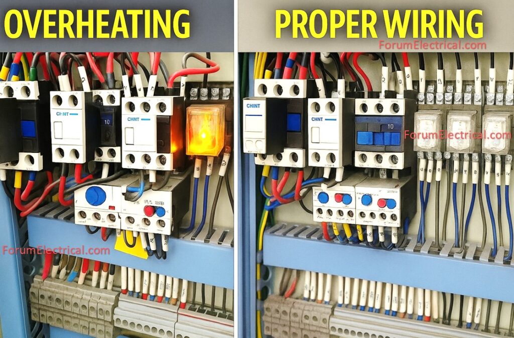
3). Overheating Components
Causes: Causes include overcurrent, clogged ventilation, and inadequate wires.
Effects: Insulation, relays & contactors will be damaged and there is a risk of fire.
Solution: Provide adequate cooling, use thermal cameras to detect hotspots, and install fans (or) heat exchangers.
4). Ground Faults
Causes: Causes include damaged insulation, moisture infiltration or conductor contact with the earth.
Effects: Effects include nuisance tripping, excessive leakage current, and a safety concern.
Solution: Test insulating resistance with a megger to find leaking sites.
5). Faulty control devices (contactors, Relays and Timers)
Causes: Causes include coil burnout, mechanical damage and carbonized contacts.
Effect: Incomplete circuit operation (or) failure of automation routines.
Solution: Replace faulty coils, clean the connections and verify the coil voltage ratings.
6). PLC (or) Automation System Failures
Causes: Causes include software errors, power fluctuations, communication issues and I/O failures.
Effect: Process halt (or) faulty execution of automation logic.
Solution: Examine PLC error logs, backup programs and check I/O module functionality.
Control Panel Troubleshooting Procedure (Step by Step)
Troubleshooting electrical faults necessitates a methodical and safety-focused procedure.
Step 1: Visual inspection
Step 2: Verify Power Supply Integrity
Step 3: Check the Circuit Protection Devices
Step 4: Test Electrical Components
Step 5: Verify the Control Circuit
Step 6: Diagnose PLC & Automation Systems
Step 7: Final Test & Load Run
Before performing any diagnostic work always adhere to the Lockout-Tagout (LOTO) procedures and applicable safety regulations such as IEC 60204-1, NFPA 70E & IS/IEC 60947.
Step 1: Visual inspection
Check for burn marks, melted insulation (or) discoloration of components.
Loose or unconnected wires and terminal screws.
Moisture, dust accumulation (or) corrosion within the panel.
Cables, fuses & breakers should be properly labeled according to the schematic.
Use proper illumination & an inspection mirror in restricted locations.
Step 2: Verify Power Supply Integrity
Use a digital multimeter to measure the incoming voltage.
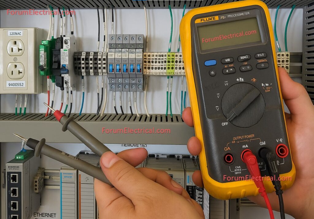
Confirm the right phase sequence and balance.
Eg: at 415V, three-phase system should read around 400V and 430V phase to phase.
Check that neutral & grounding connections are tight & free of oxidation.
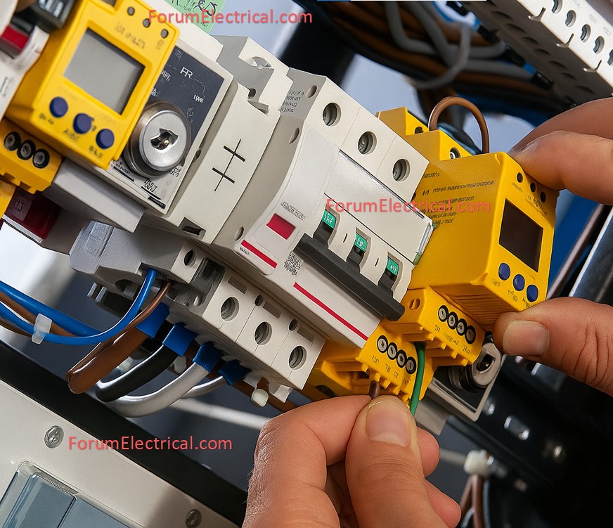
Step 3: Check the Circuit Protection Devices
Check all MCBs, MCCBs, fuses & ELCBs for evidence of tripping or damage.
If the breakers trip frequently utilize a clamp meter to determine the load current.
Monitor trip time & current magnitude to differentiate between overload & short-circuit conditions.
Utilize thermal-magnetic trip curves to assess protective properties.
Step 4: Test Electrical Components
Contactors and Relays
Test electrical components including contactors and relays.
Use an ohmmeter to measure coil resistance.
When you power the coil check for contact continuity.
Motors and Drives
For motors and drives, test insulation resistance with a megger (500V or 1000V).
Check the motor winding continuity & phase balance.
Cables and Terminals
For cables and terminals inspect for continuity and insulating integrity.
Replace damaged conductors & re-terminate with appropriate cable lugs.
Step 5: Verify the Control Circuit
Follow the control wiring diagram (or) schematic to trace the circuit.
Eg: if a contactor coil does not energize make sure it is receiving its rated voltage (24V DC or 230V AC).
Monitor transient signals in control circuits using a multimeter’s hold function.
Step 6: Diagnose PLC & Automation Systems
Connect your PLC programming software (such as Siemens TIA Portal, Allen Bradley RSLogix or Schneider EcoStruxure).
Check the I/O status LEDs & fault codes on the modules.
Check the ladder logic (or) function block diagram for the programming errors.
Check communication settings (Modbus, Profibus, Ethernet/IP) & cable integrity.
Step 7: Final Testing
After repairs (or) replacements test the system in operational settings.
Re-energize the control panel and maintain track of all loads.
Use an infrared thermal camera to locate hotspots in terminals & busbars.
Use a power quality analyzer to track harmonics, imbalance, and voltage drops.
Keep a maintenance log with all test results and observations for verification.
Safety Precautions for Control Panel Troubleshooting
Always wear arc flash PPE (gloves, face shield and insulated tools).
Use insulating mats and obstacles.
Follow LOTO procedures & put safety signs.
Keep fire extinguishers (CO₂ or dry powder) easily accessible.
Guidelines for Avoiding Upcoming Electrical Faults
Conduct routine thermographic checks to detect early indicators of overheating.
Carry preventive maintenance every three to six months.
Maintain appropriate cable management & ventilation.
After making changes to the control panel wiring diagram make sure to update it regularly.
Install surge protectors (SPDs) & voltage monitoring relays.
Utilize high-quality electrical components that meet IEC and IS requirements.
Practical Illustrations
A 33kV substation control panel repeatedly tripped the auxiliary breaker. Engineers detected loose neutral terminals during an inspection resulting in intermittent phase imbalance.
After retightening & retesting the system stabilized with the balanced voltages of 440V across phases avoiding future tripping.
Conclusion
Troubleshooting electrical failures in control panels is a technical and safety extremely important activity.
An organized diagnostic procedure ranging from visual inspection to extensive component testing provides accurate fault diagnosis and system recovery.
Electrical engineers can reduce downtime, improve reliability, and extend the life of equipment by implementing preventive maintenance according to international safety standards & using modern diagnostic tools.