
Step potential is a term often applied when it comes to electrical engineering safety concerning the electrical voltage like in the electrical substations or where electrical faults are likely to occur.
- What is Step Potential?
- Step Potential Test Procedure
- Equipment Requirement
- Step-by-Step Procedure
- Step-1: Connect the E Lead
- Step-2: Insert the Injector Electrode
- Step-3: Position Two Electrodes for Step Potential
- Step-4: Start the Test
- Step-5: Calculate Step Potential Voltage
- Why do ground faults occur in the test area?
- What are the Essentials for a Test?
- What You Will Measure?
- How to Calculate the Potential Difference?
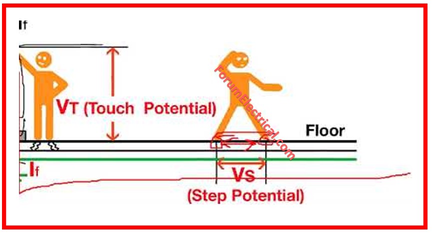
- Difference between Step Potential and Touch Potential
- Step Potential vs Touch Potential
It relates to the electrical potential (voltage) that could potentially endanger a person stepping into areas with voltage gradients that might be induced by equipment or system malfunction.
Whenever a backward fault exists in a compartment of an electrical system, the potential of the ground close to that fault section is charged at different voltages in the different areas due to the flow of the fault current.
Whenever a person is close to such places with different ground potentials and later transfers his feet across these areas, they may feel the electric voltage that can cause an electric shock or be injured depending on the potential difference across the feet if it is above certain limit values.
What is Step Potential?
Using the concept of difference in surface potentials at the position of the feet, step potential is described as that difference which a person experiences when he bridges a gap of one step which is approximately one meter or 3 feet without coming in direct contact with any grounded object.
Consequently, it becomes one of the chief factors to contemplate when determining the safety of electrical applications and devices.
Equipotential grounding grids or mats may provide means to decrease the step potential or electrical shock hazards in high-voltage working areas: equipotential to each other, different sections might have sudden voltage variations if a person steps on a different area.
If there is an electrical fault and there is a variation in the AC voltage between one foot and the ground, the amount that is met when someone steps into the particular area is referred to as step potential, the reason why it is important to consider step potential as an aspect of electrical safety particularly where there is high voltage.
A method that is used in order to detect the ground faults is called Step Potential Testing.
When it comes to considerations of safety in the field of electrical engineering, one of the most important phenomena to analyze is the possibility of ground faults, particularly in fields exposed to the presence of electrical equipment and systems.
Electrostatic hazards and TSP testing is a procedure used in assessing the risks of such areas.
This post will disclose when ground faults can be expected near the area to be tested, which tools you should use, what measurements you will make, and how to calculate the potential voltage for safety evaluation.

Step Potential Test Procedure
When it comes to electrical safety inspection specifically of grounds that are potentially at risk of experiencing a ground fault, doing a Step Potential Test as a precaution is also a must.
The following general procedure describes the process of doing a Step Potential Test in the most efficient manner.
However, you must note that handling electrical systems is dangerous; thus, safety should be the utmost priority at all times.
Equipment Requirement
- Grounding systems with an E lead to capacitance.
- Injector electrode (used to simulate the anticipated type of fault).
- 2 electrodes arranged at a distance of 30 inches, which is the typical measure of a step a man takes.
- Coupling leads (Es and S leads) to connect the electrodes.
- 4-pole Ground Resistance Tester.
Step-by-Step Procedure
Step-1: Connect the E Lead
A good starting point is the joining of the E lead with the grounding system. This lead will be your working reference for the test.
Step-2: Insert the Injector Electrode
Find out the distance from the grounding system at which you expect the fault to be taking place, preferably in meters.
This is where you will ‘throw’ the fault, obviously this means imitating a fault to test the reaction of the kitchen.
The injector electrode must be inserted at this point.
Attach one wire of the H lead from the Ground Resistance Tester to the injector electrode.
Step-3: Position Two Electrodes for Step Potential
Now, take two electrodes and put them one step apart as a human being is about three feet.
These electrodes should be placed at the anticipated position of a person’s foot during the test.
Fasten the Es and S leads from the Ground Resistance Tester to these electrodes.
Step-4: Start the Test
Perform the Ground Test Mode with four points on the Ground Resistance Tester.
Start the test and note down the resistance reading given by the tester.
Step-5: Calculate Step Potential Voltage
Determine the anticipated value of the fault current (I). Depending on the circumstances, it might differ substantially, which is why it’s highly useful to have at least some notion of the type of faults that may happen.
Step potential voltage (V) is arrived at by converting the measure value of the resistance (R) and multiplying it with the estimated fault current (I).
The formula is: When it comes to converting investment into volume, the relationship is expressed by the formula
V = I x R
Thus, the procedure referred to as Step Potential Test ensures you find out how much voltage difference will likely be experienced by a person taking a step from one point to another particularly due to faults in the electrical system and resulting difference in ground potential.
This information is important in establishing the risks faced by employees in such working conditions and to check if protective measures are well implemented to prevent electric shock risks.
Why do ground faults occur in the test area?
The electrons in the ground fault are looking for the area to be tested and therefore they may make contacts to leak through and give the ground a low resistance.
This is a kind of fault that occurs when an electric current seeks for the ground inappropriately. In areas with electrical equipment or systems, there are several reasons why ground faults are reasonably expected near the testing location or equipment grounded by the ground being tested.
In areas with electrical equipment or systems, there are several reasons why ground faults are reasonably expected near the testing location or equipment grounded by the ground being tested:
Wear and Tear: Electrical systems and their equipment are bound to degrade through time because of age, environmental forces or mechanical strain. This wear and tear usually results in insulation failure and laying of grounds.
Corrosion: Corrosion causes soldered and other electrical connections and grounding systems to fail enhancing the prospects of ground faults.
Environmental Factors: The hazards like moisture, dust or any chemicals also affect the insulation of electrical systems which provides path to ground.
Overloads and Short Circuits: Isolation between phases and between phases and ground can be disrupted by electrical overloads and short circuits leading to ground faults.
Improper Installation (or) Maintenance: Flaws when installing an electrical system or even poor practices in maintaining it will lead to additional vulnerabilities in the power systems and thus induce more ground faults.
What are the Essentials for a Test?
Testing is actually the procedure of clearing the confusion about the bugs and glitches and understanding the framework of the content and structural form that one has been creating from the initial stage to the current stage.
The following tools are required for Step Potential Testing:
- A 4-pole Ground Resistance Tester: This device is employed to find the resistance of the ground in ohms.
- Three Auxiliary Electrodes and Test Leads for Step Potential Testing: These electrodes are put on the ground in appropriate spacing to measure step potentials, that is, the voltage a person might touch when taking a step in the area.
- Two Auxiliary Electrodes for Touch Potential Testing: These electrodes assist in estimating the touch voltage which is the potential that a person would feel if he or she touched an electric object in the vicinity.
What You Will Measure?
The values that you are likely to get from the Ground Resistance Tester concerning Step and Touch potential will be obtained in ohms.
These measurements are very vital in determining the electrical safety of the ground since they represent the resistance of the ground.
How to Calculate the Potential Difference?
Preliminary, in order to evaluate the level of the threat posed by the measured resistance, it is possible to evaluate likely fault current, and then multiply it by the measured resistance to obtain voltage.
The potential voltage shows how severe the environment is in the case of a ground fault.
Higher potential voltage is more dangerous to personnel and equipment to be insulated.
Also, Touch and Step Potential Testing is an important practice that forms part of electrical safety that is used to determine the risk of ground faults on the areas with electrical equipment or systems.
Keep in consideration that ground faults can happen and when doing your calculations and measurements for ground resistance and possible voltage, coupling with having the right equipment and knowing why ground faults can happen, you can then determine the risks in such environments and avoid harm to human beings and equipment.
Difference between Step Potential and Touch Potential
Step Potential vs Touch Potential
| Perspective | Step Potential | Touch Potential |
| Definition | Difference in voltage of two points on the earth. | Potential difference between an object and the earth or between two points of a circuit. |
| Condition | It happens that the current flows through the ground, for example, when one of several phases of the power line falls on the ground or during a lightning strike. | Happens when an individual comes into contact with a live conductor that is in contact with the earth |
| Human Communication | Risk exist when one is on the floor either standing or walking on it | Risk happens when you are in contact with a live wire. |
| Voltage Difference Location | In between the arches of an individual’s feet whenever they stand on the ground. | Between a tangible (grounded) object and the foot of a person |
| Dangers | Electric shock through the legs, possible severe injury or death | Shocking from hand to feet with a possibility of getting severely shocked or even dying. |
| Typical Situations | Situation like; broken power pylons, cases of lightning strikes | Live metal structures or objects that conducts electricity as a result of electrical faults |
| Safety Measures | Grounding, avoiding proximity to the equipment, sturdy insulations and warning signs | Grounding, equipotential bonding, insulation, sign boards |
| Examples | An example of voltage division is a person walking close to an electrode which is a fallen power line and the voltage level varies between the soles of his/her feet. | A person is touching an energized fence when is on the ground |


