
Current Transformers (CTs) are essential components in electrical power systems.
- What is CT Saturation?
- Important Characteristics of CT Saturation
- Causes of CT Saturation
- 1). High Primary Current (Fault Current)
- 2). DC Offset in Fault Current
- 3). Excessive CT Burden
- 4). CT Operating Beyond Knee Point Voltage (KPV)
- 5). Poor Magnetic Core Material
- 6). Improper Installation
- Problems Caused by CT Saturation
- 1). Protection System Problems
- 2). Metering Problems
- 3). Equipment Stress and Damage
- Mitigation of CT Saturation
- 1). Proper CT Selection
- 2). Burden Management
- 3). DC Offset Compensation
- 4). Saturation Resistant CTs
- 5). Proper Installation
- 6). Advanced Relay Techniques
- Applicable Standards
- Table: CT Saturation Causes, Problems & Mitigation Techniques
- Summary
They are utilized to step down high primary currents to lower measurable values for
- Protective relays,
- Energy meters,
- Monitoring systems and
- Control equipment.
However, one of the most important issues associated with CTs is CT Saturation.
When saturation occurs the current transformer cannot accurately generate the primary current in its secondary winding.
This can result in
- Relay maloperation,
- Incorrect metering,
- Equipment stress and
- Even major power system failures.
Understanding CT saturation causes, problems and mitigation techniques is essential for electrical engineers involved in the power system protection, substation design and relay coordination.
What is CT Saturation?
CT saturation occurs when the magnetic core of a current transformer reaches its magnetic limit & cannot respond linearly to increasing primary current.
Under normal operating conditions the CT secondary current is proportional to the primary current.
However when the magnetic flux exceeds the cores linear operating range the CT enters saturation.
Important Characteristics of CT Saturation
- Secondary current becomes distorted.
- The waveform becomes non-linear.
- Protection relays receive the incorrect current values.
- Metering devices generate inaccurate readings.
This condition is particularly dangerous during fault conditions where accurate current measurement is essential for the system protection.
Causes of CT Saturation
CT saturation occurs when the magnetic flux in the core exceeds the CTs linear operating capability.
Several electrical and installation factors can cause this condition.
1). High Primary Current (Fault Current)
2). DC Offset in Fault Current
3). Excessive CT Burden
4). CT Operating Beyond Knee Point Voltage (KPV)
5). Poor Magnetic Core Material
6). Improper Installation
1). High Primary Current (Fault Current)
During electrical faults such as short circuits the primary current can increase dramatically.
- Fault current may reach 10-20 times the rated current,
- The CT core cannot handle this high flux,
- The magnetic core quickly reaches saturation.
Typical fault conditions
- Busbar faults,
- Transformer internal faults,
- Transmission line faults &
- Motor short circuits.
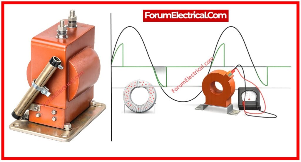
2). DC Offset in Fault Current
Fault currents often contain a DC component due to the system asymmetry.
Effects of DC Offset
- Shifts the magnetic operating point of the current transformer (CT) core.
- Causes asymmetric saturation.
- Saturation occurs in half cycles.
This is one of the most common causes of CT saturation during power system faults.
3). Excessive CT Burden
The burden of a CT refers to the total impedance connected to the CT secondary circuit.
Burden Includes
- Protection relays
- Energy meters
- Indicating instruments
- Secondary wiring resistance
- Terminal connections
If the total burden exceeds the CT rating the CT should generate higher secondary voltage which can push the core into saturation.
4). CT Operating Beyond Knee Point Voltage (KPV)
The knee point voltage is the voltage level at which the CT core starts to saturate.
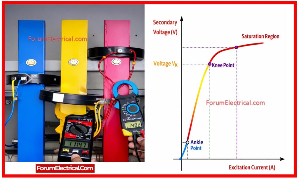
Knee Point Characteristics
- Below knee point can leads to linear operation
- Above knee point can leads to rapid saturation
If the CT is forced to operate beyond this point the secondary current becomes severely distorted.
5). Poor Magnetic Core Material
The magnetic material utilized in CT cores affects saturation characteristics.
Poor Core Materials
- Saturate very quickly
- Having low magnetic permeability
- Cause an inaccurate current generation
High quality materials which include grain oriented silicon steel improve CT performance.
6). Improper Installation
Incorrect installation practice can also lead to CT saturation.
Common Installation Problems
- Long secondary cables
- Loose connections
- Incorrect polarity
- Open circuited secondary winding
- Improper grounding
An open secondary circuit is especially dangerous because it can generate extremely high voltages.
Problems Caused by CT Saturation
CT saturation can significantly impact the power system protection and measurement accuracy:
1). Protection System Problems
2). Metering Problems
3). Equipment Stress and Damage
1). Protection System Problems
Protection relays depend on the accurate current signals.
When CT saturation occurs the relay may receive incorrect current values.
Common Protection Issues
Relay Failure to Trip: Fault currents may appear smaller because of saturation.
Delayed Tripping: Protective devices respond slower than required.
False Tripping: Harmonics that are generated during saturation may cause unwanted relay operation.
Differential Protection Errors: CT saturation may generate false differential currents in transformer protection schemes.
2). Metering Problems
CT saturation can also affect the measurement accuracy.
Metering Errors include
- Incorrect current (CT) measurement
- Energy meter inaccuracy reading
- Power factor (PF) calculation errors
- Distorted waveform readings
This may lead to billing errors & incorrect system monitoring.
3). Equipment Stress and Damage
Repeated CT saturation can create stress on the electrical equipment that causes potential damage like:
- Core overheating
- Insulation deterioration
- Permanent magnetic core damage
- Reduced CT lifespan
In severe conditions CTs may require replacement (or) recalibration.
Mitigation of CT Saturation
Proper design, installation and protective relay configuration may significantly reduce the risk of CT saturation that are:
1). Proper CT Selection
2). Burden Management
3). DC Offset Compensation
4). Saturation Resistant CTs
5). Proper Installation
6). Advanced Relay Techniques
1). Proper CT Selection
Selecting the correct CT specification is essential.
Key Selection Parameters
- CT accuracy class
- Rated burden (VA)
- Knee point voltage
- Fault current capability
- Protection class rating
Example
Protection CTs such as Class PX, PS (or) P-class CTs are designed to handle high fault currents.
2). Burden Management
The total burden connected to the CT secondary circuit would always remain within the CT rating.
Recommended Practices
- Reduce secondary wiring length,
- Utilize low resistance cables,
- Minimize number of connected devices,
- Verify the total VA burden.
3). DC Offset Compensation
Modern numerical relays include DC offset filtering algorithms.
These algorithms are:
- Detect asymmetric currents,
- Filter DC components,
- Maintain accurate protection decisions.
4). Saturation Resistant CTs
Specially designed CTs provide a better performance during the fault conditions.
Common Types
- Protection Class CTs,
- Low leakage flux CTs &
- High knee-point voltage CTs.
These CTs maintain accuracy even during large fault currents.
5). Proper Installation
Correct installation practices can prevent many CT problems.
Installation Best Practices
- Ensure a tight terminal connections,
- Maintain the correct polarity,
- Use an appropriate cable sizes,
- Keep secondary leads short &
- Never open CT secondary under load.
6). Advanced Relay Techniques
Modern digital relays can detect CT saturation patterns.
Smart Relay Features
- Saturation detection algorithms,
- Harmonic filtering,
- Adaptive protection settings and
- Waveform analysis.
These techniques prevent the false tripping and relay malfunction.
Applicable Standards
Several international standards define CT saturation, mitigation and performance requirements
| Standard | Description |
|---|---|
| IEC 61869 | Instrument Transformers Standard |
| IEC 60044 | Current Transformer Standard (older) |
| IEEE C57.13 | Instrument Transformer Standard |
| IEEE C37.110 | Guide for Application of CTs in Protection |
| IEC 60255 | Protection Relay Standard |
| IEEE C37 Series | Power System Protection |
Table: CT Saturation Causes, Problems & Mitigation Techniques
| Parameters | Descriptions |
|---|---|
| Main Causes | High fault current, DC offset, excessive burden, CT beyond knee point voltage, poor core material & improper installation |
| Protection Problems | Relay maloperation, delayed tripping & false differential current |
| Metering Issues | Inaccurate readings, power measurement errors & distorted signals |
| Equipment Risks | Heating, insulation damage & reduced CT life |
| Mitigation Methods | Proper CT selection, burden control, DC offset filtering, saturation-resistant CTs, correct installation & advanced digital relays |
Summary
CT saturation is a major concern in the power system protection and metering. This occurs when the magnetic core exceeds its linear operating limit.
The common causes include high fault current, DC offset, high burden and poor installation.
CT saturation may lead to relay maloperation, incorrect metering & equipment damage. These problems may be effectively mitigated by the proper CT selection, installation procedures and also modern relay technologies.
