Designing electrical systems is not easy as breaker sizing (or) cable selection.
One parameter, usually ignored, has a direct bearing on protection performance and on whether a circuit disconnects within the time required by the applicable standard: Fault Loop Impedance which is commonly denoted Zs.
Understanding how Zs governs disconnection times is essential for any electrical system designer who wants to achieve both regulatory compliance and genuine system safety.
What is Fault Loop Impedance (Zs)?
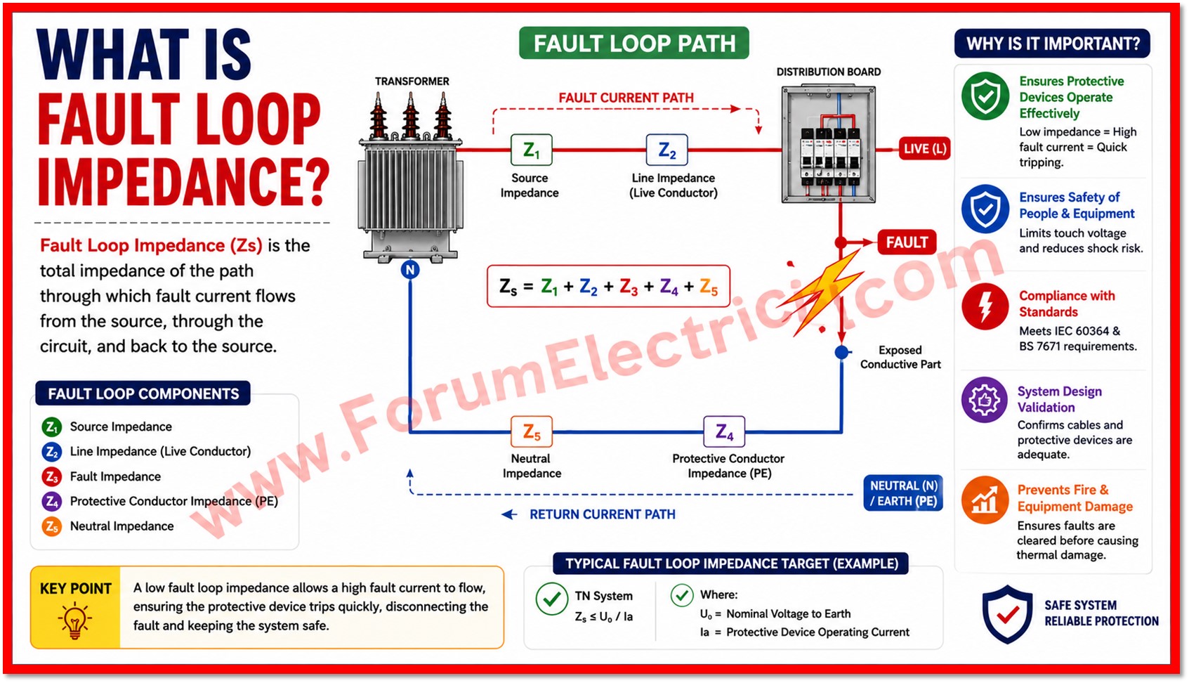
Zs is the total impedance of the fault current path.
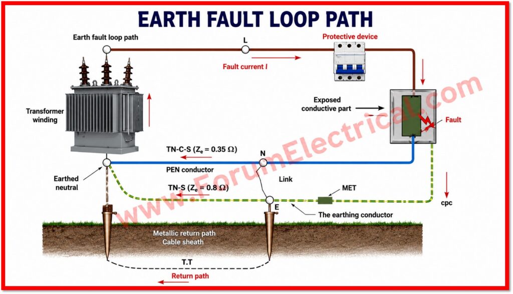
It starts at the supply source flow through the phase (line) conductor to the point of the fault which continues through the fault itself and returns through the protective earth conductor back to the source.
In other terms Zs represents the complete electrical circuit that a fault current should traverse during an earth fault event.
This value is not academic.
It directly determines whether a circuit breaker (or) other protective device can clear a fault fast enough to prevent danger.
Standards such as IEC 60364 & BS 7671 set out maximum permissible disconnection times for different circuit types typically 0.4 seconds for final circuits supplying socket outlets (or) portable equipment and 5 seconds for distribution circuits though exact figures depend on voltage, earthing arrangement and circuit classification.
If Zs is too high even a correctly selected and correctly rated breaker may fail to disconnect the circuit within the required time.
A high loop impedance limits the fault current that can flow which in turn delays (or) prevents the operation of the overcurrent (or) residual protection.
The practical consequence is prolonged exposure of both equipment and personnel to fault voltage, increasing the risk of electric shock, fire (or) equipment damage.
Factors that Influence Zs
Zs is never a fixed, catalog value.
It is the outcome of a chain of design decisions and it evolves as the design evolves.
Every change in cable routing, panel location (or) protective device selection alters the final Zs result at the point being assessed.
The principal contributing factors are:
- Cable length and cross-sectional area are longer runs and smaller conductors increase resistance and therefore Zs.
- Conductor material that the copper provides lower resistivity than aluminum for a given cross-section directly affecting the impedance contribution.
- Installation method and grouping of conduit, trunking, ambient temperature and grouping with other circuits affect the effective conductor resistance through derating & thermal effects.
- Transformer (or) source impedance having the internal impedance of the supply transformer (or) generator sets the baseline impedance before any distribution wiring is even considered.
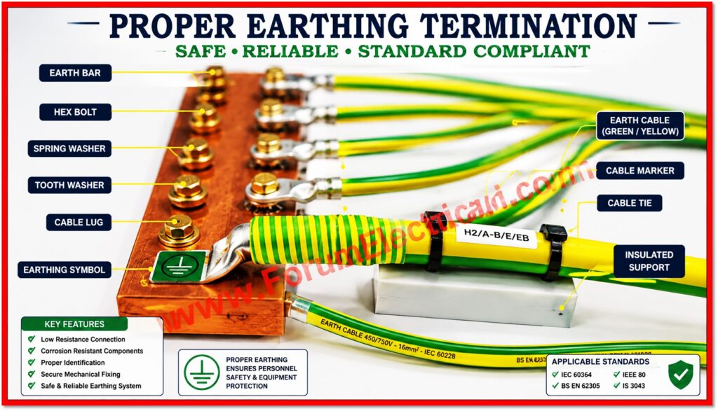
- Earthing systems which TN, TT (or) IT arrangements each establish a different fault current return path and therefore a different relationship between Zs and disconnection time.
Because these factors interact, Zs should be treated as a live design variable rather than a value that is checked once and forgotten.
A design that is compliant at concept stage can drift out of compliance as routing is finalized and as panels are relocated (or) as cable sizes are adjusted for other reasons such as voltage drop (or) thermal rating.
Practical Design
In practice calculating Zs for every single final circuit in a large building is rarely feasible and is not typically how experienced designers approach the problem.
Instead, a zoning method is commonly used to manage Zs across an entire distribution network efficiently:
- The building is divided into zones based on the location of electrical rooms and distribution boards.
- Each zone is sized so that the electrically farthest point within it still falls within the allowable Zs limit for its protective device.
- Distribution boards are positioned near the center of their zones specifically to control and minimize cable lengths to the furthest loads.
- Protective devices & cable sizes are then selected in combination to maintain Zs compliance across the whole zone rather than being verified circuit by circuit.
This zoning approach simplifies the design effort considerably while still respecting fault disconnection criteria across the entire network.
It also provides a useful early check: if a zone farthest point cannot be brought within limits through reasonable cable sizing that is a signal the electrical room location, panel position (or) zone boundary itself requires to be reconsidered rather than attempting to compensate with oversized conductors alone.
Zs & Its Function in Cross-Discipline Coordination
Fault loop impedance is not confined to the electrical discipline.
Because Zs is directly sensitive to cable length and routing path it inevitably influences decisions that sit at the boundary between electrical design and architecture (or) broader MEP coordination.
The location of electrical rooms, for example, is rarely a purely architectural decision ; placing a room too far from the loads it serves can push Zs beyond acceptable limits for the far end of its zone.
Similarly, the distribution of loads across a floor plate and the layout of main corridors determine how cable trays and containment can be routed and fed back into achievable cable lengths and therefore into Zs.
A change made purely for architectural (or) spatial reasons late in a project that is moving a riser, reshaping a corridor (or) relocating a plant room can silently undermine a Zs calculation that was valid at an earlier design stage.
For this reason, Zs deserves a seat at the coordination table early in the design process not just as a verification step at the end.
Electrical designers who flag Zs-sensitive zones early give architects and MEP coordinators the information they require to avoid costly rework later.
Calculator
Conclusion
Electrical protection is more than the act of selecting a breaker rated for the expected load.
Fault loop impedance is a more important and sometimes underappreciated function in every distribution design and it is the parameter that ultimately determines whether protection actually works in the timeframe required to keep people and equipment safe.
Careful planning which is treated as an ongoing discipline rather than a one-time check keeps Zs values within safe and acceptable limits throughout the life of a project from concept design through detailed routing to final commissioning and testing.

