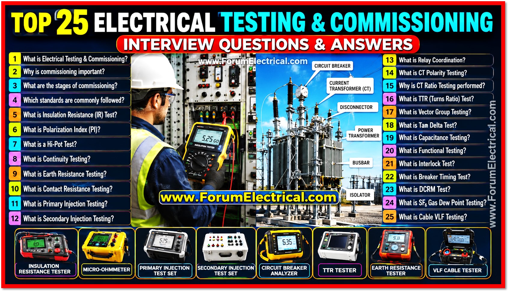
1). What is Electrical Testing and Commissioning?
Electrical Testing and Commissioning is a systematic procedure carried out to inspect, test, verify and validate electrical equipment before it is placed into service.
The objective is to ensure that the installation complies with design specifications, applicable IEC/IEEE standards and operates safely and reliably.
2). Why is Commissioning important?
Commissioning is an essential procedure in every electrical project because it confirms that all equipment has been installed correctly and functions as intended before energization.
It helps improve system safety, reliability and long term performance.
- Ensures equipment is installed correctly.
- Detects installation defects.
- Prevents equipment failure.
- Verifies protection systems.
- Improves system reliability.
- Confirms compliance with safety standards.
3). What are the stages of Electrical Commissioning?
Electrical commissioning is typically carried out in a sequence of well defined stages to ensure the safe & successful operation of the electrical system.
- Visual Inspection,
- Mechanical Inspection,
- Electrical Testing,
- Functional Testing,
- Protection Relay Testing,
- Energization,
- Performance Testing and
- Final Documentation & Handover.
4). Which standards are commonly followed during testing and commissioning?
Electrical testing and commissioning activities are performed in accordance with internationally recognized standards to ensure safety, quality and regulatory compliance.
- IEC 60076 – Power Transformers,
- IEC 62271 – High-Voltage Switchgear and Controlgear,
- IEC 60364 – Electrical Installations,
- IEEE C57 – Transformer Standards,
- IEEE 43 – Insulation Resistance Testing,
- IEEE 81 – Grounding System Testing,
- NFPA 70E – Electrical Safety in the Workplace and
- IEC 60529 – IP Protection Ratings.
5). What is an Insulation Resistance (IR) Test?
An Insulation Resistance (IR) Test is performed to evaluate the condition of electrical insulation by measuring the resistance between conductors & earth using an insulation resistance tester (Megger).
Typical test voltages include:
- 500 V
- 1000 V
- 2500 V
- 5000 V
Higher insulation resistance values generally indicate healthy insulation with minimal leakage current.
6). What is Polarization Index (PI)?
The Polarization Index (PI) is an important diagnostic test procedure utilized to assess the overall condition & dryness of electrical insulation by comparing insulation resistance values over time.
Formula
PI = 10-minute IR / 1-minute IR
Typical acceptance values:
- PI > 2.0 – Good insulation
- PI = 1.5 – 2.0 – Acceptable insulation
- PI < 1.5 – Poor insulation
7). What is a Hi-Pot Test?
A High Potential (Hi-Pot) Test is conducted to verify the dielectric strength of electrical insulation by applying a voltage significantly higher than the equipments normal operating voltage for a specified period.
This test used to identify insulation weaknesses before the equipment is energized.
8). What is Continuity Testing?
Continuity Testing is performed to confirm that electrical conductors, cables and circuits provide a complete electrical path without any open circuits (or) broken connections.
This test is commonly carried out using:
- Digital Multimeter and
- Low Resistance Ohmmeter
9). What is Earth Resistance Testing?
Earth Resistance Testing is conducted to measure the resistance between the grounding system and the surrounding soil to ensure an effective fault current path and personnel safety.
Common testing methods include:
- Fall of Potential Method
- Clamp-on Earth Resistance Method
Typical acceptable values are:
- Less than 1 Ω for substations
- Less than 5 Ω for buildings
10). What is Contact Resistance Testing?
Contact Resistance Testing is performed to measure the electrical resistance across circuit breaker contacts, busbar joints and other current carrying connections using a micro-ohmmeter.
High contact resistance may indicate:
- Loose connections
- Oxidized contact surfaces
- Worn contacts
- Poor mechanical joints
11). What is Primary Injection Testing?
Primary Injection Testing is performed by injecting a high current into the primary circuit to verify the performance of current transformers, circuit breakers, busbars and protection systems under actual operating conditions.
This test is used to verify:
- CT ratio
- Breaker operation
- Protection relay performance
- Overall primary circuit integrity
12). What is Secondary Injection Testing?
Secondary Injection Testing is carried out by injecting low current & voltage signals directly into protection relays without energizing the primary equipment.
This test is mainly performed to verify:
- Relay settings,
- Pickup values,
- Trip characteristics,
- Timing accuracy and
- Protection logic.
13). What is Relay Coordination?
Relay Coordination is the step of selecting and setting protective devices so that the device closest to the fault operates first while upstream devices remain in service.
Proper coordination helps:
- Minimize power interruptions.
- Improve system selectivity.
- Protect electrical equipment.
- Enhance system reliability.
14). What is CT Polarity Testing?
CT Polarity Testing is performed to verify that the primary and secondary terminals of a current transformer are correctly identified and connected according to the polarity markings.
Incorrect polarity may result in:
- Relay maloperation,
- Incorrect metering,
- Differential protection failure and
- False tripping.
15). Why is CT Ratio Testing performed?
CT Ratio Testing is conducted to confirm that the current transformer accurately converts primary current into the specified secondary current according to its nameplate ratio.
This test helps detect:
- Incorrect CT connections,
- Shorted turns,
- Manufacturing defects and
- Calibration errors.
16). What is Transformer Turns Ratio (TTR) Test?
The Transformer Turns Ratio (TTR) Test is performed to verify the turns ratio between the primary and secondary windings of a transformer.
This test helps identify:
- Shorted turns,
- Open windings,
- Incorrect tap changer position and
- Winding deformation.
17). What is Transformer Vector Group Testing?
Transformer Vector Group Testing is carried out to verify the phase relationship and phase displacement between the high voltage (HV) and low voltage (LV) windings.
Common vector groups include:
- Dyn11
- Dyn1
- YNd11
- Yyn0
18). What is Tan Delta Test?
The Tan Delta Test, also known as the Dissipation Factor Test is performed to evaluate the dielectric losses of electrical insulation and determine its overall condition.
It is commonly used for:
- Power Transformers,
- Bushings,
- Current Transformers,
- Voltage Transformers,
- Power Cables and
- Generators.
Lower Tan Delta values generally indicate better insulation quality.
19). What is Capacitance Testing?
Capacitance Testing is conducted to measure the capacitance of electrical insulation and detect any physical (or) electrical changes in the insulation system.
This test helps identify:
- Moisture ingress
- Winding displacement
- Insulation deterioration
- Internal defects
20). What is Functional Testing?
Functional Testing is performed to verify that all electrical equipment, protection devices, control circuits and automation systems operate correctly under normal operating conditions.
Typical functional tests include:
- Circuit breaker operation
- Relay tripping
- PLC logic verification
- SCADA communication
- Alarm and annunciation checks
- Remote control operation
21). What is an Interlock Test?
An Interlock Test is carried out to ensure that electrical equipment can only operate under safe operating conditions and that unsafe operations are prevented.
Common interlock checks include:
- Breaker cannot close when the earthing switch is closed.
- Earthing switch cannot close while the breaker is ON.
- Door interlocks.
- Mechanical and electrical key interlocks.
22). What is Breaker Timing Test?
Breaker Timing Testing is performed to measure the opening time, closing time and synchronization of circuit breaker contacts during operation.
The test evaluates:
- Closing time,
- Opening time,
- Pole discrepancy and
- Contact synchronization.
It is performed using a Circuit Breaker Analyzer.
23). What is Dynamic Contact Resistance Measurement (DCRM)?
Dynamic Contact Resistance Measurement (DCRM) is a specialized test performed on circuit breakers to measure contact resistance while the breaker is operating.
This test helps identify:
- Arcing contact wear,
- Main contact damage,
- Mechanical defects and
- Contact erosion.
24). What is SF₆ Gas Dew Point Testing?
SF₆ Gas Dew Point Testing is performed to measure the moisture content present inside SF₆ gas filled switchgear and circuit breakers.
Excessive moisture may lead to:
- Flashover
- Reduced dielectric strength
- Internal corrosion
- Equipment failure
25). What is Cable VLF Testing?
Very Low Frequency (VLF) Testing is performed on medium voltage and high voltage power cables to evaluate insulation integrity using a low frequency AC test voltage.
This test helps detect:
- Insulation defects
- Water treeing
- Cable ageing
- Installation damage

