Forward/reverse control of a three-phase induction motor is one of the most common requirements in industrial automation that is found on conveyors, crushers, mixers, hoists and general material handling equipment.
Mostly implemented with relay logic and this function is now using a Programmable Logic Controller (PLC) which brings flexibility, diagnostics and easy modification without rewiring.
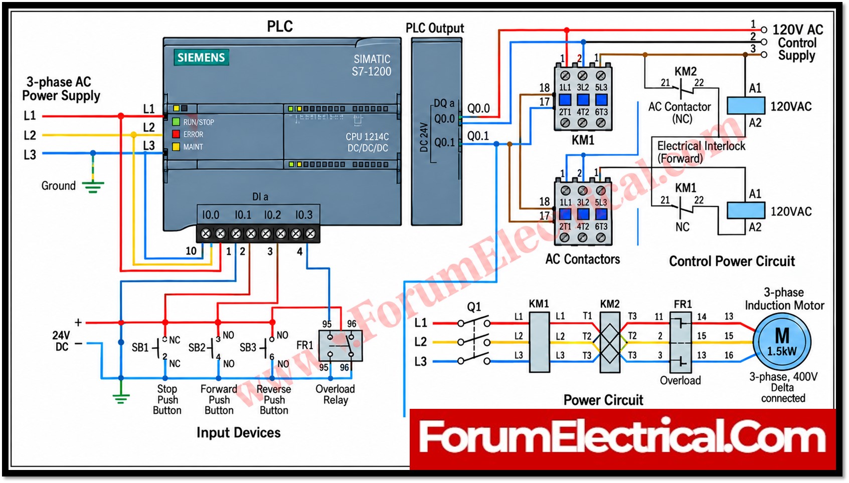
This post describes in detail a PLC-based forward/reverse motor control system covering its input section, control logic, output and interlocking circuit, power circuit and protection features.
Input Section (Control Signals)
All field devices that generate operator (or) protection signals are wired to the digital input module of the PLC that is powered from a 24 V DC control supply and the standard voltage level for PLC I/O due to its safety and noise immunity advantages over primary voltage.
The input devices used in this system are:
- Stop Pushbutton (Normally Closed): Wired as a safety loop so that the input is continuously energized during normal operation. A broken wire, loose connection (or) pressed button all result in a de-energized input and the PLC logic is written to treat loss of this signal as a stop command which is a fail-safe design principle.
- Forward Pushbutton (Normally Open): Momentary contact that commands forward rotation when pressed.
- Reverse Pushbutton (Normally Open): Momentary contact that commands reverse rotation when pressed.
- Overload Relay Auxiliary Contact: A feedback signal from the motor thermal (or) electronic overload relay informing the PLC that an overcurrent (or) fault condition has occurred so that outputs can be withdrawn immediately.
Components
- 3-Phase supply (L1, L2, L3),
- MCB / Fuse protection,
- Forward Contactor (KM1),
- Reverse Contactor (KM2),
- Thermal Overload Relay (FR1) and
- 3-Phase Induction Motor.
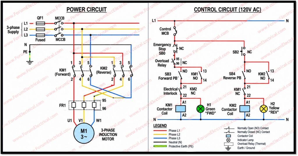
The motor direction changes by reversing two phases using KM1 and KM2 contactors.
This arrangement ensures that every safety important signal is hardwired to the PLC rather than assumed allowing the control program to make functioning based on real and monitored field conditions.
PLC Control (Logic & Processing)
A compact PLC (commonly a fixed I/O unit such as a Siemens LOGO/S7-1200, Allen-Bradley Micro800, Delta DVP or similar) executes the control program.
The logic typically follows a seal-in (latching) structure for each direction that is built from standard ladder logic rungs:
- Pressing Forward sets a Forward memory bit that provided Stop is not active and Reverse is not already running.
- The Forward output seals itself in through its own contact and so the pushbutton only requires to be pressed momentarily.
- Pressing Reverse follows the same logic for the reverse direction and mutually exclusive with Forward.
- Pressing Stop (or) an overload trip, resets both Forward and Reverse memory bits unconditionally.
Requirements
PLC Control Wiring
- PLC Controller (e.g., Siemens S7-1200),
- Digital Inputs for push buttons,
- Digital Outputs controlling contactors,
- Electrical interlocking through auxiliary contacts and
- Overload feedback to PLC for fault protection.
Inputs
- Stop Push Button,
- Forward Start Push Button,
- Reverse Start Push Button and
- Overload Relay Feedback.
Outputs
- Forward Contactor (KM1),
- Reverse Contactor (KM2) and
- Status Indicator Lamps.
- Green Lamp → Motor running Forward
- Yellow Lamp → Motor running Reverse
A software interlock is included in the ladder logic itself and the Forward rung includes a normally closed contact of the Reverse output (and vice versa) and so that even before the physical contactor interlock is considered, the PLC program itself avoids both outputs from being true at the same time.
This is the first of 2 independent layers of interlocking in the system.
Output & Interlocking Circuit
The PLC digital outputs drive the coils of the forward and reverse contactors either directly (for relay-type/low-current transistor outputs within the contactor coils rating) (or) through interposing relays which is the more common and strong industrial practice since it isolates the PLC output card from the inductive switching load of the contactor coil.
The hardwired layer of interlocking is implemented using normally closed auxiliary contacts of each contactor which is wired in series with the coil circuit of the opposite contactor.
This means that even if the PLC program were to malfunction (or) a signal fault caused both outputs to energize simultaneously and the forward contactor NC auxiliary contact physically breaks the reverse contactor coil circuit, and vice versa.
This electromechanical interlock is an important safety redundancy as it does not depends on software and protects against both logic errors and contact welding conditions.
Many installations add a third layer which is mechanical interlocking between the contactors for maximum assurance.
Power Circuit (Motor Side)
The three-phase supply reaches the motor through the main contacts of the forward and reverse contactors and the overload relay current-sensing elements.
In forward mode, the incoming phases L1, L2 and L3 are connected to the motor terminals in their natural sequence (U, V, W), generating rotation in the forward direction.
In reverse mode, any two of the three phases are physically interchanged at the contactor wiring commonly L1 and L3 while the third phase remains unchanged.
This phase reversal changes the rotating magnetic field direction inside the stator which reverses the direction of motor rotation.
This is a purely electrical technique and requires no mechanical change to the motor itself which is the reason for reversing duty motors and conveyor drives that depends on this method.
Protection & Safety Measures
The overload relay continuously monitors the current drawn by the motor on all three phases.
If the current exceeds the relay set trip value for a sustained period indicating conditions such as mechanical jamming, single-phasing (or) prolonged overload that the relay trips, opening its contact and simultaneously signaling the PLC input.
The control program responds by de-energizing both forward and reverse outputs immediately stopping the motor regardless of which direction it was running in.
The Stop pushbutton being wired as a normally closed safety loop provides an equally immediate and dependable shutdown path.
Together these 2 protection mechanisms:
- One for operator-initiated stops and
- One for automatic fault detection
ensure that the system fails to a safe, de-energized state under any abnormal condition.
Working Principle
| Operator Action | System Response |
| Press Forward | PLC sets Forward output → Forward contactor closes → Motor runs forward |
| Press Reverse | PLC sets Reverse output → Reverse contactor closes → Motor runs in reverse |
| Press Stop | PLC resets both outputs → Contactors open → Motor stops instantly |
| Overload Trip | Fault signal reaches PLC → Outputs de-energized → Motor stops, fault flagged |
PLC Ladder Logic for Forward/Reverse Motor Control
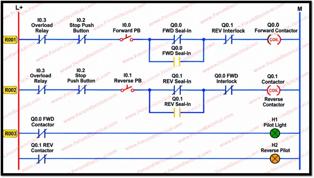
This diagram represents the PLC ladder logic used to control forward and reverse motor operation.
R001 – Forward Control
The first rung controls the forward contactor Q0.0.
The logic includes:
I0.3 – Overload Relay
I0.2 – Stop Push Button
I0.0 – Forward Push Button
Q0.0 – FWD Seal-In
Q0.1 – REV Interlock
Q0.0 – Forward Contactor Coil
When the forward push button is activated and all permissive conditions are satisfied, Q0.0 is energized.
The Q0.0 seal-in contact maintains the forward command after the push button is released.
R002 – Reverse Control
The second rung controls the reverse contactor Q0.1.
It contains:
- Overload relay input
- Stop push button
I0.1 – Reverse Push Button
Q0.1 – REV Seal-In
Q0.0 – FWD Interlock
Q0.1 – Reverse Contactor Coil
The forward and reverse interlocks ensure that the PLC does not command both contactors simultaneously.
R003 – Motor Status Indication
The third rung provides motor-direction indication using pilot lamps.
- H1 – Forward Pilot Light
- H2 – Reverse Pilot Light
The contactor status signals are used to indicate the commanded operating condition.
Overall Operation
The sequence is:
Stop → Select Forward/Reverse → PLC Processes Inputs → Interlock Check → Contactor Output → Motor Direction
The PLC-based arrangement provides programmable control, electrical interlocking logic, status indication and easier modification compared with conventional hardwired relay control.
Applications
This control architecture is widely deployed wherever equipment requires to run in 2 directions with safety essential interlocking including:
- Belt and screw conveyors requiring forward/reverse material transport.
- Crushers & shredders needing reverse operation to clear jams.
- Mixers and agitators requiring bidirectional blending cycles.
- Gate and door drives, hoists and general material-handling machinery.
Conclusion
A PLC-Based Forward/Reverse Motor regulate System is a safe, dependable and effective way to regulate a three-phase induction motor.
The system uses electrical and software interlocking, overload protection & PLC ladder logic to avoid forward and reverse contactors from operating at the same time while maintaining smooth motor control.
It is frequently employed in conveyors, hoists, pumps and various other industrial automation applications that require accurate and reliable motor control.

