
Programmable Logic Controllers (PLCs) are the primary one of modern industrial automation, providing reliable, repeatable control over the machinery ranging from simple conveyor belts to complex process lines.
At the major function of every PLC operation is the scan cycle a continuous loop through which the controller reads inputs that executes the programmed logic, updates outputs and then repeats the process which is typically within milliseconds.
One of the most fundamental and widely used applications of this scan cycle is the classic motor Start/Stop circuit that forms the foundation for countless
- Motor starters,
- Pumps,
- Compressors and
- Conveyor systems across industry.
This post explains how the PLC scan cycle interacts with ladder logic to control a motor Start/Stop circuit safely & efficiently.
What is a PLC Scan Cycle?
A scan cycle is the sequence of operations a PLC performs over and over to maintain its outputs synchronized with real world conditions.

Rather than executing instructions only once the PLC continuously repeats a defined sequence of steps so that any change in an input device such as a pushbutton (or) sensor is detected and acted upon almost instantly.
This cyclical function is that allows a PLC to provide real time control despite relying on sequential processing of ladder rungs.
The speed of the scan which is often just a few milliseconds per cycle means that from an operators perspective the response of the motor to the Start (or) Stop pushbutton appears immediate.
The scan cycle can be broken down into 4 primary stages that is summarized below:
| Stage | Operation | Description |
| 1 | Input Scan | The PLC reads the status of all connected input devices including the Start pushbutton, Stop pushbutton, overload relay contact and any interlocks and stores their states in the input image table. |
| 2 | Program Execution | The processor solves the ladder logic rung by rung, evaluating the Start, Stop and seal in contacts against the input image table to determine the required state of the motor contactor output coil. |
| 3 | Output Update | The calculated coil status is written to the output image table and then transferred to the physical output module, energizing (or) de-energizing the contactor coil that drives the motor starter. |
| 4 | Housekeeping and Repeat | The processor performs internal diagnostics, communication servicing and watchdog timer resets before returning to Stage 1 completing the cycle typically within a few milliseconds. |
Motor Start/Stop Circuit Fundamentals
Before examining how the PLC processes this logic it helps to understand the underlying control circuit concept that is derived from traditional relay-based motor starters.
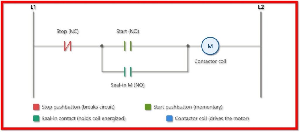
In a typical arrangement, a Start pushbutton, a Stop pushbutton and a seal-in or holding contact work together with a contactor coil to control the motor.
Start Pushbutton
A normally open contact that, when pressed, allows current to flow to the contactor coil, energizing it and starting the motor.
Seal-In (Holding) Contact
An auxiliary contact wired in parallel with the Start pushbutton. Once the contactor coil energizes this contact closes & maintains the current path even after the Start button get released.
Stop Pushbutton
A normally closed contact placed in series with the rest of the circuit. Pressing it opens the circuit, de-energizing the coil and breaking the seal-in path, which immediately stops the motor.
Contactor Coil & Output
The output device that switches the heavy motor current on and off, controlled by the small-signal logic described above.

This arrangement is often referred to as a three-wire control circuit because it depends on three connections, Start, Stop, and the seal-in feedback, to maintain a latched, self-holding condition rather than requiring the operator to hold the Start button continuously.
Conversion of Circuit into Ladder Logic
When this hardwired control scheme is implemented in a PLC each physical device is represented as a ladder logic element on a single rung.
The Start pushbutton becomes a normally open input contact, the Stop pushbutton becomes a normally closed input contact and the contactor coil becomes an output coil instruction.
A parallel branch containing a normally open contact mapped to the same output address as the coil that recreates the seal-in function entirely within software.

During each scan the processor evaluates this rung from left to right.
If the Start contact is closed (or) if the seal-in contact is already closed from a previous scan and the Stop contact remains closed (meaning the Stop pushbutton is not pressed, since it is normally closed) then the rung condition is true & the output coil is commanded on.
This logical structure sometimes called ‘latching logic’ allows the PLC to hold the motor running indefinitely after a momentary Start signal exactly as the physical seal-in contact would in a relay circuit.
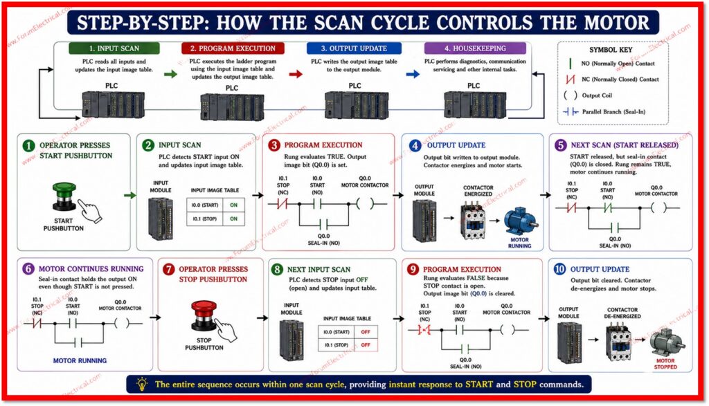
Step-by-Step: How the Scan Cycle Controls the Motor?
Step-1: Consider the sequence of events when an operator presses the Start pushbutton.
Step-2: During the input scan stage the PLC is used to detect that the Start input has transitioned to a closed state & updates the input image table accordingly.
Step-3: During the program execution the processor is used to evaluate the motor control rung. Since the Start contact is now closed & the Stop contact remains closed (not pressed), the rung logic evaluates as true and the internal output image bit for the contactor coil is set.
Step-4: During the output update stage this bit is written to the physical output module, energizing the contactor & starting the motor.
Step-5: On the following scan even if the operator has already released the Start button, the seal-in contact which mirrors the now-energized output coil is closed.
Step-6: This maintains the rung condition true without requiring the Start contact to remain closed, so the motor continues running. This is the software equivalent of the seal-in relay holding itself in.
Step-7: When the Stop pushbutton is pressed, its normally closed contact opens.
Step-8: On the next input scan the PLC registers this change.
Step-9: During program execution the rung condition becomes false since the series Stop contact is now open that regardless of the state of the Start (or) seal-in contacts.
Step-10: The output coil bit is cleared, and during the output update stage the contactor de-energizes that stopping the motor.
Because this entire sequence occurs within a single scan cycle, the response to the Stop command is essentially instantaneous from an operational standpoint.
Why the Scan Cycle important for Safety and Reliability?
The scan cycle is central to the safety and reliability of motor control applications.
Because the PLC continuously re-evaluates the Stop condition on every single scan, a Stop command is never missed (or) delayed by more than one scan interval which is typically just a few milliseconds.
This predictable timing allows engineers to safely integrate additional safety interlocks such as
- Emergency stop circuits,
- Overload protection and
- Interlocking with other equipment
Additionally because the scan cycle processes inputs, logic and outputs as separate, ordered stages, the PLC avoids the kind of race conditions (or) inconsistent states that can occur in purely asynchronous hardwired systems.
Every function the processor makes during a given scan is based on a consistent snapshot of input conditions captured at the start of that same scan.
Applications
The Start/Stop scan-cycle logic described above is one of the most widely deployed control patterns in industrial automation.
It forms the basis of direct-on-line motor starters used on pumps, fans and compressors and is extended with additional rungs for conveyor systems requiring interlocked sequencing, manufacturing cells needing coordinated multi-motor operation and process control systems where motor status feeds back into higher-level supervisory logic.
Its simplicity, reliability and ease of troubleshooting make it a standard building block that automation engineers encounter in virtually every industrial control system.
Conclusion
The PLC scan cycle transforms a simple, well-understood relay control concept, the three-wire Start/Stop circuit with seal-in logic into a strong, repeatedly verified software routine.
By continuously
- Scanning inputs,
- Executing ladder logic and
- Updating outputs within a matter of milliseconds
the PLC ensures that motor start and stop commands are executed accurately and safely, cycle after cycle.
Understanding this relationship between the scan cycle and ladder logic rungs is essential for anyone working with motor starters, conveyor systems, pumps, compressors (or) any other application where dependable Start/Stop functionality is required.

