
What is meant by Electronic Ballast?
An electronic ballast, also referred to as an electrical ballast, is a component of equipment that controls the starting voltage & currents of the lighting fixtures.
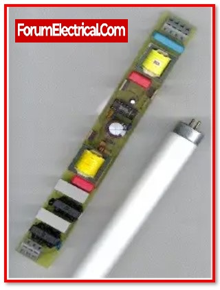
This is accomplished by the use of the electrical gas discharge technique. To start the gas discharge method in fluorescent lamps, an electronic ballast converts the power frequency to a very high frequency by managing the voltage across the bulb and current through the lamp.
Block Diagram of Electronic Ballast
The electronic ballast’s basic block diagram is shown below.
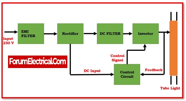
The block diagram of the electronic ballast has five blocks, as shown in the image above. In general, all electronic ballasts adhere to that block diagram.
1). EMI Filter
The Electromagnetic Interference filter is represented by Block 1. EMI filters are made out of inductors and capacitors that block or minimise electromagnetic interference.
2). Rectifier
The rectifier circuit is represented by Block 2. The rectifier circuit converts alternating current to direct current.
3). DC filter
DC filter circuit is represented by Block 3. A capacitor is the component of the DC filter circuit that is responsible for filtering the impure DC that is generated by the rectifier circuit.
4). Inverter
The inverter circuit is represented by Block 4. The DC is converted to high-frequency AC in this block, and a step-up transformer raises the power level.
5). Control Circuit
The control circuit, represented by Block 5, receives feedback from the output and regulates the rectifier, filter, & inverter circuits. The majority of electronic ballasts lack this block.
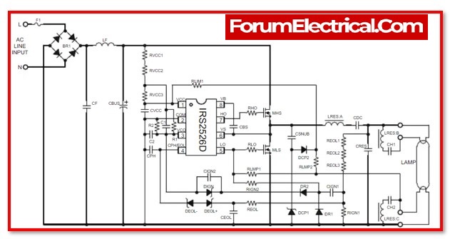
Circuit Diagram of Electronic Ballast
The IRS2526DS “Mini8″Ballast Control IC is the focal point of the design for a 26 W electronic ballast circuit that does not use PFC. The light as well as the half bridge resonant output stage are both fully controlled by the circuit. The frequency of the ‘HO’ and ‘LO’ pins, which are outputs from the half-bridge gate driver, is adjusted by the ‘VCO’ pin. Programming the required VCO voltage levels requires a resistor voltage divider to be placed at the ‘VCO’ pin. The frequency of the internal voltage-controlled oscillator is determined by the values of these voltage levels. The signal from the internal oscillator is then sent into the logic circuitry of the high-side and low-side gate drivers. This allows the necessary preheat, ignition, and operating frequencies to be generated for the half-bridge & resonant output stage. For the purpose of providing a consistent lamp ignition voltage and identifying a lamp end-of-life fault setting, a lamp voltage resistor divider (REOL1, REOL2, REOL3, RIGN1) & feedback circuit (CIGN1, DR1, DR2, DIGN, REOL, CEOL, DEOL+, DEOL-) are used.
Electronic Ballast Working Principle
Electronic ballasts need power at 50 – 60 Hz. It initially transforms the alternating current voltage to direct current voltage. Following that, the DC voltage is filtered using a capacitor arrangement. The filtered DC voltage is now sent into the high-frequency oscillation stage, where the oscillation is normally square wave and the frequency range is 20 kHz to 80 kHz.
As an outcome of this, the frequency of the output current is extremely high. To create a high value, a little quantity of inductance is given to be coupled with an elevated rate of change of the current at a high frequency.
More than 400 V is often needed to initiate the gas discharging process in the fluorescent tube lights. When the switch is turned on, the initial supply of voltage across the bulb reaches 1000 V owing to the high value, and gas discharge occurs instantly.
When the discharge process begins, the voltage across the bulb is reduced from 230V to 125V, and the electronic ballast permits a restricted current to flow through the light.
The control unit of electronic ballast controls the voltage and current. When fluorescent lights are turned on, the electronic ballast functions as a dimmer, limiting current and voltage.
Performance of Electronic Ballast
Different metrics are used to evaluate the effectiveness of electronic ballasts.
The Ballast Factor is the most important. It is the ratio of the lamp’s light output when driven by the ballast under examination to the lamp’s light output when driven by the reference ballast.
For electronic ballasts, this value is reported to range between 0.73 and 1.50.
A single ballast can provide a large variety of light output levels, which is the relevance of such a broad range.
This has many of uses in dimming circuits. However, it has been shown that both excessively high and excessively low ballast factors reduce lamp life owing to lumen degradation brought on by high & low lamp currents, respectively.
Ballast Efficacy Factor, which is the ratio of ballast factor (in %) to the power & provides a relative measurement of the system efficiency of the entire lamp ballast combination, is frequently used when comparing electronic ballasts from the same model and manufacturer.
Ballast operation efficacy is measured using the Power Factor (PF) metric. The electronic ballast’s ability to convert supply voltage & current into useable power and deliver it to the light is measured by its power factor, with 1 being the optimal value. In contrast, low power factor ballasts would need nearly twice as much current as higher power factor ballasts & hence support fewer lights in a circuit. This does not, however, indicate the ballast’s capacity to provide light.
Every electrical device has a limit to how linear it can be, & when the input signal exceeds that limit, the signal is distorted, resulting in non-linear & harmonic distortions. Harmonic distortion, which is assessed as Total Harmonic Distortion, is said to have occurred when the signal waveform deviates from the typical sinusoidal shape.
The harmonic current added by electronic ballasts to the power distribution system as a percentage is known as THD. Although the ANSI standards permit a maximum distortion of up to 32%, most manufacturers strive to maintain THD below 20%. It is simpler to maintain distortions at these levels using electronic ballasts than it is with magnetic (or) hybrid ballasts.
Advantages of Electronic Ballast
- Ballast dependability declines with time; the longer it is in use, the lower its failure probability. Compared to magnetic ballasts, the power of the lights declines more gradually when utilised with electronic ballasts.
- These gadgets are not only significantly lighter and more effective, but also much quieter.
- When compared to magnetic (or) hybrid ballasts, power loss with electronic ballasts is approximately half as great.
- Additionally, owing of the high bulb voltage needs, they may easily run lights that cannot be driven directly by a choke on the line.
- In lamp-ballast systems, energy efficiency may be improved primarily in three ways: by reducing ballast losses, operating at higher frequencies, & reducing lamp electrode losses. Electronic ballasts are more energy efficient since they include all three of these features at once.
Disadvantages of Electronic Ballast
- Electronic ballasts generate strong harmonic current from alternating current spikes around voltage maximums. This may create stray magnetic fields, pipe corrosion, radio and TV interference, and IT equipment failure, in addition to lighting system issues.
- High harmonic content may overload three-phase transformers and neutral wires. The human eye may not detect a greater flicker rate, but infrared remote controls for home entertainment equipment like TVs .
- Intelligent ballast documentation and design reduces interference in application frequency ranges.
- However, there are certain undiscovered nooks in frequency spectrum that are not employed in any application, and most ballast disturbances in this area are ignored, generating a cleaner image on paper than itscertainty.
- Electronic ballasts cannot handle power spikes and overloads.
- Electronic ballasts also have a high initial cost, which may deter impulsive buyers, but they cost more than for it over time.
Application of Electronic Ballast
1). Keep the output power constant
Maintain the steady output power of the lights. The technique of square-wave current driving ensures that no “acoustic resonance” phenomena occur.
2) Abnormal protection
When the electronic ballast operated with the lamp, it is typical for tubes to leak, not activate, not start, the primary circuit current to be too high, and other abnormalities to occur. When an exception arises in the illumination, the electronic ballast will cut off automatically to ensure the ballast’s and the light’s safety.
3). Controls the over-current and over-voltage
When the quality of the power supply is poor, the grid will experience various serious phenomena such as harmonics & noise pollution (such as transient high voltage, high energy pulse), or the switch will be unable to be used due to lightning, the ballast can protect the lamp better through voltage and current regulation.
4). Reduce the temperature rise
When the ballast temperature increases drastically after lengthy hours of activity, it may reduce the life expectancy of the ballast. You should aim to minimise power usage and enhance efficiency throughout the design process.
An electronic insulating plastic (insulating material) may decrease the overall temperature of the product, prevent water, dust, and other debris from entering, avoid short circuit damage induced by moisture damage to the object, and further improve the product’s reliability, but it cannot prevent damage caused by transport vibration and shock. In general, the electrical efficiency of a high-performance electronic ballast is more than 90%.
5). Wide operational voltage range
Voltage is unstable in certain distant places, and power quality is low. Yet, the ballast can regulate the voltage to maintain regular lamp illumination even when the voltage fluctuates dramatically.
6). Adjust the crest factor of the light current
The lamp current crest factor is a significant indication that may affect cathode emission capabilities and launch current stability. With a stronger lamp current crest-factor and a shorter lamp, & the ability to add more flash.