
Three-phase motors are widely utilised in industrial & commercial applications due to their efficiency & performance.
However, there are times when a three-phase motor must run on a single-phase source of electricity. This could be due to a number of factors such as a lack of power, retrofitting existing systems, (or) specific uses.
In such condition, a Variable Frequency Drive (VFD) can be utilised to run a three-phase motor from a single-phase power source.
With the help of the wiring and control circuit schematics provided, let demonstrate how to run a 3-phase motor on a 1-phase supply in reverse-forward & ON/OFF operation using a VFD.
Converting Three-Phase Motors: A VFD Solution for Single-Phase Power
Motors with three phases are intended to run on three separate phases of alternating current (AC), each of which is rotated by an angle of 120 degrees relative to the other two phases. When opposed to single-phase motors, this design provides a more seamless functioning as well as increased efficiency.
Because there is not enough of a phase difference between the two phases of the supply, a three-phase motor that is connected to a single-phase supply will not start and will not function as designed.
When this occurs, need a variable frequency drive, or VFD, in order to run a three-phase motor on single-phase power supply.
Function of VFD
A variable frequency drive (VFD) is an electrical device that can vary the speed and torque of an alternating current (AC) motor by altering the frequency & voltage of the supplied electricity.
VFDs are frequently employed in industrial applications to conserve energy, optimise motor control, and allow motors to operate on multiple power supply.
In this configuration, it will employ a VFD capable of converting a 1-phase supply into a 3-phase supply in order to operate a three-phase load on a single-phase power supply.
Required Components
- Three-Phase Motor
- Braking Resistor – speed control of motor (Optional)
- Single-Phase Supply
- Variable Frequency Drive (VFD)
- MCB
- Wires & Cables
- Selector Switch (Manual ON/OFF & REV/FWD Operation)
- Programmable logic controller (PLC) – controlling VFD’s operation
How to Run a Three-Phase Motor on a Single-Phase Supply utilising a VFD?
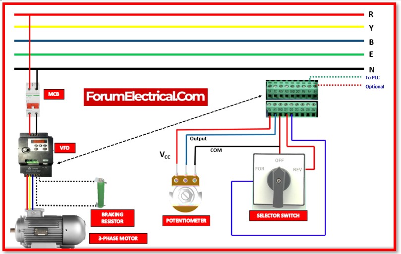
Power Connection
- Select a VFD that can work with both a three-phase motor and a single-phase power supply.
- The VFD should be able to transform the single-phase input into the three-phase output by adjusting the frequency and voltage. To connect the power circuit:
- Interconnect the 100-230V AC single-phase supply of power that comes from the 2-P MCB to the VFDs using two wires labelled “L” (Line or Phase), “N” (Neutral), and Ground/Earth.
- Attach the three-phase motor terminals (U1, V1, and W1) to the VFD’s U, V, and W output terminals. Check that the phases are matched & in the correct order.
Electrical Control Wiring
Connect additional control devices (which include ON/OFF and REV/FWD switches, indicators, PLCs, and so on) to the control digital inputs of the variable frequency drive (VFD).
The following procedures need to be taken in order to regulate the speed of a three-phase motor utilising a single-phase power source in reverse and forwards directions:
- Join the reverse terminal of the selector switch to the DI1 input.
- Establish a connection between the forwards terminal of selector switch and the DI2 input.
- Establish a connection between the AI1 and the Output terminal of the potentiometer, and then connect 10V to VCC terminal.
- Connect the common (GND) terminal of the potentiometer to the OFF terminal of the selector switch and the common (GND) terminal of the VFD.
- In addition,have the option of connecting the A+ & B+ to the exterior PLC by making use of the RJ45 connector.
- Ideally, have the option of connecting a breaking resistor to the P+ & PB terminals located on the VFD.
Function of Motor
Access the control panel (or) software interface of the VFD and configure the parameters for single-phase operation of a three-phase motor.
Typically, this involves setting input power specifications, motor parameters, and the intended operating frequency.
Start the motor using the VFD’s control panel or interface after confirming all connections and configurations.
The VFD converts the single-phase input power into simulated three-phase output power using a frequency and voltage that can be adjusted.
Monitor the performance of the motor and adjust the VFD’s parameters to accomplish the desired speed, torque, & efficiency.
In order to optimise the motor’s operation on the single-phase supply, fine-tuning may be required.
The selector switch can be utilised to turn the motor ON, OFF, forwards, and backwards.
External and optional devices, such as a braking resistor and programmable logic controller (PLC), can be utilised for speed control & variable frequency operation, etc.


