The UPS is capable of working in a variety of various modes, the selection of which is determined by the availability of the rectifier mains, bypass mains, battery voltage, and the load that currently is applied (actual load).
These modes include:
Normal operation Mode
Battery operation Mode
Static bypass operation Mode
Charging only operation Mode
Standby Mode
Off Mode
Maintenance or Manual Bypass(MBS) mode – TEST position
Maintenance or Manual Bypass(MBS) mode – Bypass position
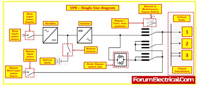
Single line diagram of UPS
The diagram that can be viewed below provides a visual representation of the basic structure that defines the UPS.
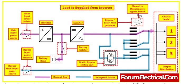
Normal operation Mode
In the normal operation mode of a UPS (Uninterruptible Power Supply), several key functions ensure a continuous and reliable power supply to the connected load.
Figure demonstrates how an inverter supplies power to the load during normal operation. Here’s how this mode operates:
Firstly, the manual/maintenance bypass switch (MBS) remains in the “AUTO” position during normal operation.
This configuration allows for seamless and automatic transitions between various power sources, ensuring uninterrupted power delivery.
The AC input, also known as the rectifier mains, is the primary source of power for the UPS during normal operation.
This electricity flows through a Power Factor Correction (PFC) rectifier. The PFC rectifier plays a critical role in stabilizing the mains voltage, compensating for fluctuations and load changes, and maintaining a consistent DC voltage level.
The rectifier not only supplies power to the inverter but also keeps the connected battery in standby mode.
This includes managing the battery’s charging state through processes like float charge and boost charge, which depend on the battery’s condition and type.
This ensures that the battery is always ready to provide backup power in case of an outage.
The downstream inverter is responsible for converting the DC voltage from the rectifier into AC voltage suitable for the connected load.
This conversion utilizes optimized sine wave pulse width control (PWM) techniques, ensuring a high-quality and stable AC output.
The UPS inverter provides a seamless transition from mains power to battery power without interruptions, protecting sensitive equipment from voltage sags, surges, or outages.
During normal UPS operation, a continuous and reliable power supply is maintained by efficiently managing the AC input, battery backup, and inverter to ensure that the connected load receives clean and uninterrupted electrical power, safeguarding critical equipment and preventing downtime.
S.No
Concerns – Normal Operation mode
Status – Normal Operation mode
1
Main input power to rectifier
Available and within the limits(tolerance)
2
Main input power isolator
Closed position
3
Bypass input main power
Available and within the limits(tolerance)
4
Bypass input power isolator
Closed position
5
Manual /Maintenance bypass switch(MBS) position
Auto position
6
Battery bank
Available and within the acceptable range (the battery’s charging state may be in recharge mode), depending.
7
Battery isolator
Closed position
8
Rectifier
ON
9
Inverter
ON
10
Static Bypass switch
OFF
11
Output Voltage
Available and within the limits(tolerance)
Battery operation Mode
What is UPS battery mode?
During battery operation mode in a UPS (Uninterruptible Power Supply), several crucial functions come into play to ensure the continuous supply of power to the connected load.
Figure illustrates how the inverter uses the battery to power the load. Here’s how this mode operates:
Manual Bypass Switch
The manual bypass switch (MBS) remains in the “AUTO” position during battery operation. This setting allows for automatic transitions between power sources.
Inverter Engagement
In the event of power sags or failures from the AC input (rectifier mains), the UPS switches to battery power seamlessly and without interruption. The inverter takes over as the power source.
Battery Discharge
The connected battery, which is part of the DC intermediate circuit, is automatically activated to supply electrical current to the load.
This ensures an uninterrupted power supply even when the main power source fails.
Monitoring Battery
The UPS continuously monitors the state of the battery. As it discharges, the battery voltage decreases based on the duration and magnitude of the discharge current.
The inverter compensates for this voltage drop, maintaining a constant output voltage to the load.
Low Battery Alarm
When the battery’s discharge limit is nearing, an alarm is activated, alerting users to the potentially limited backup time.
Recovery and Changeover Options
If the battery approaches its discharge limit, the system will automatically switch back to normal operation mode upon mains power recovery or when emergency power is generated by a diesel generator, provided it is within tolerance.
If bypass mains power is available and within tolerance, the system can switch to bypass operation.
However, if bypass mains is unavailable or outside tolerance limits, the system will initiate an automatic shutdown to protect the battery from over-discharge.
Mains Recovery and Battery Charging
When mains power is restored or when emergency power is supplied by a diesel generator, the rectifier restarts once the voltage stabilizes.
It will then initiate the battery charging process if the UPS system is programmed for “AUTOSTART” at mains recovery. If not, a manual restart is required.
Battery Current Limitation
Depending on the depth of discharge of the battery, the charge current is limited using battery current limitation methods to prevent damage or overcharging.
During battery operation mode, the UPS efficiently switches to battery power in the event of mains power failure, monitors and compensates for battery discharge, and provides options for recovery, ensuring the continuous supply of power to the connected load.
It also employs safeguards to prevent over-discharge and offers flexibility in terms of switching to bypass or shutting down based on available power sources.
S.No
Concerns – Battery operation mode
Status – Battery operation mode
1
Main input power to rectifier
Not available and within the limits(tolerance)
2
Main input power isolator
Closed position
3
Bypass input main power
Available and within the limits(tolerance)
4
Bypass input power isolator
Closed position
5
Manual /Maintenance bypass switch(MBS) position
Auto position
6
Battery bank
Available and within the acceptable range (the battery’s charging state may be in recharge mode), depending.
7
Battery isolator
Closed position
8
Rectifier
OFF
9
Inverter
ON
10
Static Bypass switch
OFF
11
Output Voltage
Available and within the limits(tolerance)
Static Bypass Operation
What is the purpose of static bypass?
Static bypass operation in a UPS (Uninterruptible Power Supply) is a crucial mode that ensures continuous power supply to connected loads under specific conditions.
Let’s break down the key points mentioned and explain both scenarios of static bypass operation: automatic change-over and manual change-over.
Manual Bypass Switch (MBS)
During static bypass operation, the manual bypass switch (MBS) is always set to the “AUTO” position, enabling automatic transitions between power sources.
Interrupt-Free Change-Over
Static bypass operation allows for a seamless and interruption-free transition of power to the direct mains power supply (bypass mains) while adhering to specified tolerances.
This change-over can be initiated either automatically by a control signal or manually by an operator.
Synchronization Requirement
Typically, to achieve an interruption-free change-over, the voltage, frequency, and phase relationship of the inverter must be synchronized with the bypass mains.
Any deviations in the mains frequency beyond specified tolerance ranges would usually prevent a smooth change-over.
However, it is possible to configure the UPS to perform an asynchronous change-over to bypass, albeit with a momentary break in power.
Manual Change-Over
Manual change-over to the bypass mains is only possible when the UPS system is synchronized with the bypass mains.
Automatic Change-Over
When the inverters cannot provide power within the specified tolerances (e.g., due to fluctuations or issues), an automatic change-over to the bypass mains occurs to ensure a continuous power supply to the load.
Bypass Mains Fault
In the event of a fault in the bypass mains during automatic change-over, the system will automatically switch back to normal operation if the rectifier main (utility power) is available.
If the rectifier mains are not available, a change-over to battery operation takes place if the battery is within the specified tolerance range.
This battery operation occurs only if the system has been manually switched to bypass operation.
Depending on the programming, a brief loss of output voltage may occur during this transition.
Load Supply
In both scenarios of static bypass operation, whether due to automatic or manual change-over, the load is directly supplied with power from the bypass mains, ensuring a continuous power supply to connected devices.
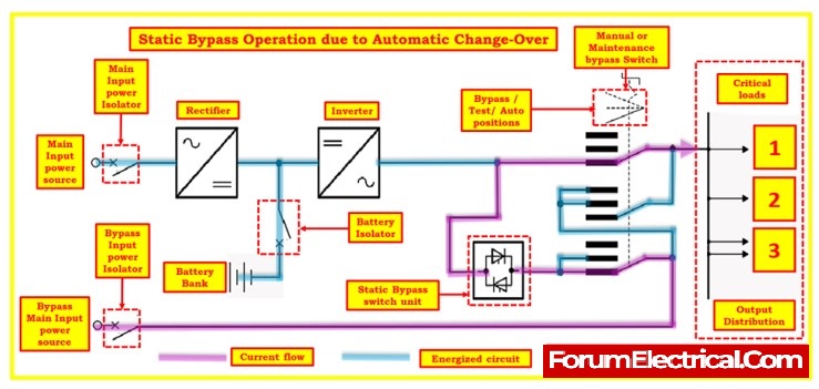
Static Bypass Operation Due to Automatic Change-Over
This occurs when the system automatically detects that the inverter cannot provide power within specified tolerances. In such cases, the UPS swiftly switches to the bypass mains to maintain power continuity to the load.
S.No
Concerns – Static Bypass Operation Due to Automatic Change-Over
Status – Static Bypass Operation Due to Automatic Change-Over
1
Main input power to rectifier
Outside the tolerance range (it may be within the tolerance range). If the inverter is overloaded and its power limit is reached, the UPS will also switch to bypass. The power source to the inverter is not guaranteed.
2
Main input power isolator
Closed position
3
Bypass input main power
Available and within the limits(tolerance)
4
Bypass input power isolator
Closed position
5
Manual /Maintenance bypass switch(MBS) position
Auto position
6
Battery bank
Outside the tolerance range (it may be within the tolerance range). If the inverter is overloaded and its power limit is reached, the UPS will also switch to bypass. The power source to the inverter is not guaranteed.
7
Battery isolator
Closed position
8
Rectifier
OFF/ON (based on the reason for the switchover)
9
Inverter
OFF
10
Static Bypass switch
ON
11
Output Voltage
Available and within the limits(tolerance)
If the overload condition is no longer present or if a potential error is resolved, the UPS will automatically switch back to either its normal mode of operation or its operation using the battery.
Static Bypass Operation Due to Manual Change-Over
Manual change-over to static bypass operation is initiated by an operator when necessary, typically in situations where maintenance or testing is required.
The load is then directly powered from the bypass mains.
S.No
Concerns – Static Bypass Operation Due to Manual Change-Over
Status – Static Bypass Operation Due to Manual Change-Over
1
Main input power to rectifier
Available and within the acceptable range Bypass operation was chosen using the HMI (Human Machine Interface).
2
Main input power isolator
Closed position
3
Bypass input main power
Available and within the limits(tolerance)
4
Bypass input power isolator
Closed position
5
Manual /Maintenance bypass switch(MBS) position
Auto position
6
Battery bank
Available and within the acceptable range Bypass operation was chosen using the HMI (Human Machine Interface).
7
Battery isolator
Closed position
8
Rectifier
ON
9
Inverter
ON
10
Static Bypass switch
ON
11
Output Voltage
Available and within the limits(tolerance)
Static bypass operation in a UPS is designed to ensure uninterrupted power supply to critical loads.
It offers both automatic and manual change-over options, considering synchronization with the bypass mains and specified tolerances.
This redundancy helps safeguard against power disruptions and is especially important in critical applications where uninterrupted power is essential.
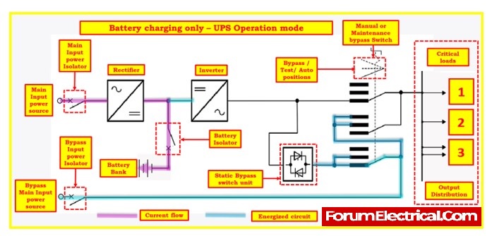
Battery Charging only operation Mode
The “Charging Only” operation mode in a UPS (Uninterruptible Power Supply) system is a specific mode where the UPS primarily focuses on charging the battery while not actively supplying power to the connected load.
This mode serves various purposes, including maintaining the battery’s health, ensuring it’s fully charged, and preparing it for potential use during power outages. Here’s an explanation of the Charging Only operation mode:
Battery Charging Priority
In this mode, the UPS system prioritizes charging the battery. It dedicates its energy to replenishing the battery’s charge level to its optimal capacity.
Available, based on the state of charge. The battery remains in the system, and its charge level is maintained or increased as needed.
No Load Supply
During Charging Only operation, the UPS does not provide power to the connected load.
The load remains powered directly by the mains (utility power) without UPS intervention.
NO output voltage (with MBS at position «AUTO»). The UPS is not providing power to the load during Charging Only operation. The load remains powered by the mains or another source.
Battery Maintenance
This mode is essential for maintaining the health and longevity of the UPS battery.
By periodically charging the battery, it remains in good condition and is ready to provide backup power when needed.
Preparing for Outages
The Charging Only mode ensures that the battery is fully charged and prepared to take over in the event of a power outage or other disruptions in the mains power supply.
This readiness is crucial for providing uninterrupted power to critical equipment during emergencies.
S.No
Concerns – Charging only operation Mode
Status -Charging only operation Mode
1
Main input power to rectifier
Available and within the acceptable range
2
Main input power isolator
Closed position
3
Bypass input main power
May or may not be available and within the limits(tolerance)
4
Bypass input power isolator
Closed position
5
Manual /Maintenance bypass switch(MBS) position
At the position “AUTO,” which might also be at the “TEST” or “BYPASS” position
6
Battery bank
available (based on the state of the charge)
7
Battery isolator
Closed position
8
Rectifier
ON
9
Inverter
OFF
10
Static Bypass switch
OFF
11
Output Voltage
NO output voltage (with MBS at position «AUTO»)
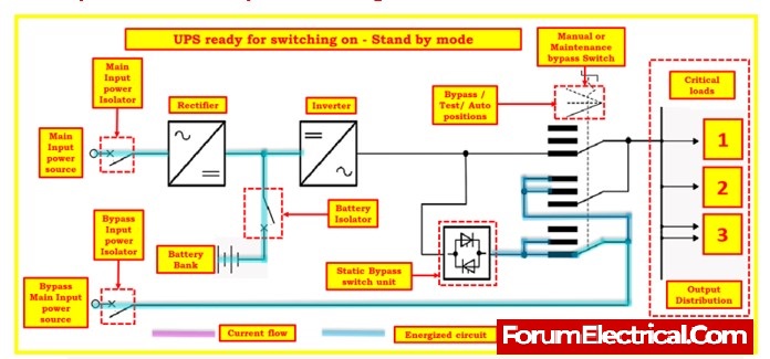
Standby Mode – UPS ready for switching on
The Standby Mode of a UPS (Uninterruptible Power Supply) represents a state of preparedness where the system is poised to swiftly respond to any power disruptions.
In this mode, the UPS ensures that the main input power from the utility grid is readily available and within acceptable voltage and frequency ranges.
The input power isolator is kept in the closed position, maintaining a connection to the utility source.
Similarly, the bypass input power, though not actively used, is monitored for availability within specified tolerance limits.
The Manual/Maintenance Bypass Switch (MBS) is typically set to “AUTO,” though it may also be configured for testing or bypass purposes.
The UPS’s battery bank is present and ready, as indicated by the closed battery isolator.
The rectifier is switched ON to facilitate battery charging. However, the inverter and static bypass remain OFF, with no output voltage supplied to the load in this mode.
This standby state ensures that the UPS is on standby to deliver uninterrupted power to critical equipment, swiftly transitioning to active mode when power interruptions occur, thereby safeguarding against potential downtime.
S.No
Concerns – Charging only operation Mode
Status -Charging only operation Mode
1
Main input power to rectifier
Available] [at least one power supply must be available]
2
Main input power isolator
Closed position
3
Bypass input main power
Available and within the acceptable range
4
Bypass input power isolator
Closed position
5
Manual /Maintenance bypass switch(MBS) position
At the position “AUTO,” which might also be at the “TEST” or “BYPASS” position
6
Battery bank
Available] [at least one power supply must be available]
7
Battery isolator
Closed position
8
Rectifier
OFF
9
Inverter
OFF
10
Static Bypass switch
OFF
11
Output Voltage
NO output voltage (with MBS at position «AUTO»)
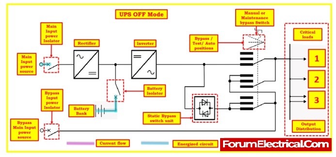
OFF Mode – UPS system OFF
The OFF Mode in a UPS (Uninterruptible Power Supply) system represents a state of complete deactivation and non-operation.
During this mode, the UPS system is disconnected from both the utility main power source and the bypass mains power source, ensuring a complete isolation from external power supplies.
Several critical conditions are observed in this state: circuit breakers, switch-disconnectors (including the manual bypass switch, MBS), and additional breakers are only actuated in accordance with commissioning guidelines.
The main input power to the rectifier is intentionally made unavailable, with the main input power isolator held in an open position, preventing any connection to the utility main power source.
Similarly, the bypass input main power is also made unavailable, with the bypass input power isolator open. The MBS(maintenance / manual bypass switch) is typically set to “AUTO,” though it may be configured for testing or bypass purposes. Furthermore, the battery bank is disconnected, and its isolator is open, ensuring the battery remains inactive.
Both the rectifier and inverter are turned OFF, rendering them non-operational, and the static bypass switch is also OFF.
As a result, there is no output voltage supplied to the load during this OFF Mode.
The UPS remains in this standby state until specific commissioning procedures are followed to reactivate it, ensuring that the system is completely prepared for any subsequent power requirements.
S.No
Concerns – Charging only operation Mode
Status – Charging only operation Mode
1
Main input power to rectifier
Not available
2
Main input power isolator
Open position
3
Bypass input main power
Not available
4
Bypass input power isolator
Open position
5
Manual /Maintenance bypass switch(MBS) position
At the position “AUTO,” which might also be at the “TEST” or “BYPASS” position
6
Battery bank
Disconnected
7
Battery isolator
Open position
8
Rectifier
OFF
9
Inverter
OFF
10
Static Bypass switch
OFF
11
Output Voltage
NO output voltage
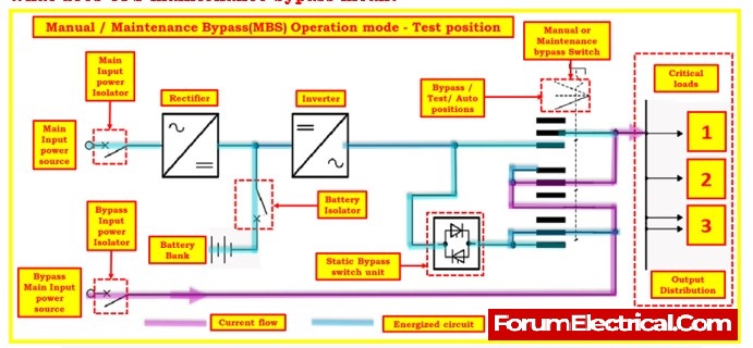
Maintenance or Manual Bypass (MBS) mode – TEST position
What does UPS maintenance bypass mean?
In the Maintenance or Manual Bypass (MBS) mode with the MBS set to the “TEST” position, the UPS system is configured for specific testing and maintenance purpose (Functional check purposes).
This mode allows for critical operations, such as synchronization of the inverter with the bypass mains and switching attempts between the Bypass and Inverter modes.
The primary purpose of the TEST position is to facilitate various tests, including the synchronization of the inverter – bypass – inverter.
This ensures that the UPS can seamlessly switch between different power sources, such as the inverter and bypass mains, without disrupting the connected load.
It allows for controlled switching attempts between the Inverter – Bypass – Inverter modes.
This is essential for verifying the UPS system’s ability to transition smoothly and quickly between power sources, which is critical for providing uninterrupted power to connected equipment during power disruptions.
The TEST position is commonly used during maintenance and repair activities on the UPS system. Technicians can perform diagnostics, check system functionality, and make necessary adjustments while ensuring that the connected load remains powered.
S.No
Concerns – Charging only operation Mode
Status – Charging only operation Mode
1
Main input power to rectifier
Available and within the acceptable range
2
Main input power isolator
Close position
3
Bypass input main power
Available and within the acceptable range
4
Bypass input power isolator
Close position
5
Manual /Maintenance bypass switch(MBS) position
At the position “TEST”
6
Battery bank
Available
7
Battery isolator
Close position
8
Rectifier
ON / OFF
9
Inverter
ON / OFF
10
Static Bypass switch
ON / OFF
11
Output Voltage
Directly supplied from the bypass mains Power
Maintenance or Manual Bypass (MBS) mode – Bypass position
What happens when UPS is in bypass mode?
In the “Maintenance or Manual Bypass (MBS) mode – Bypass position,” specific conditions and statuses are configured to facilitate repair and maintenance work inside the UPS (Uninterruptible Power Supply) system without disturbing the connected load.
Additionally, some components in the connection field and certain elements and lines may remain energized for specific purposes
Maintenance and Repair Work
The primary purpose of the “Bypass” position of the MBS is to enable repair and maintenance work within the UPS system.
It allows technicians to access and service components without affecting the load connected to the UPS.
Load Continuity
During this mode, the load is served by the bypass (alternate) source. This ensures that critical equipment connected to the UPS continues to receive power, even while maintenance activities are in progress.
The bypass mains power source acts as a backup power supply.
The MBS switch is designed as a “make before break” switch, meaning that it ensures a smooth transition from the normal mode to the bypass mode.
This design minimizes any potential disruption to the load during switching.
Inverter and Bypass
The MBS has two positions, “NORMAL” and “BYPASS.” In the “NORMAL” mode, the inverter output is connected to the load as the primary power source.
In the “BYPASS” mode, an alternate source (bypass mains) feeds the load. This allows for seamless switching between power sources as needed for maintenance.
Caution
It’s emphasized that following the correct operating procedure for the MBS switch is crucial. Incorrect operation can affect both the load and the UPS system.
Proper training and adherence to procedures are essential to ensure safe and effective maintenance.
S.No
Concerns – Charging only operation Mode
Status – Charging only operation Mode
1
Main input power to rectifier
Available and within the acceptable range or May be not be available
2
Main input power isolator
Open position
3
Bypass input main power
Available and within the acceptable range
4
Bypass input power isolator
Close position
5
Manual /Maintenance bypass switch(MBS) position
At the position “BYPASS”
6
Battery bank
Not available or disconnected
7
Battery isolator
Open position
8
Rectifier
OFF
9
Inverter
OFF
10
Static Bypass switch
OFF
11
Output Voltage
Directly supplied from the bypass mains Power
Enter your name and email and get the weekly newsletter... it's FREE!
Introduce yourself and your program
Your information will *never* be shared or sold to a 3rd party.


