
In a closed loop system, a portion of the output of the system is taken back to the input section or to the control.
The closed loop system regulates the electrical drive feature and, in general, the system adjusts itself.
In the post of the specific electrical drive, feedback loops might be added to meet the following needs:
- Improvement of the rate of torque
- To improve steady-state accuracy
- Protection
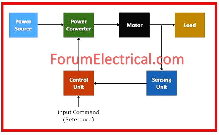
The primary components of a closed-loop system include a
- Controller,
- Converter,
- Current limiter,
- Current sensor, etc.
The converter either converts variable frequency to fixed frequency, or vice versa.
The current limiter prevents current to go higher than the maximum set value hence its main function is to limit current.
The closed loop configuration can be of following types, which are explained as follows:
Current Limit Control
This configuration is employed to prevent the amperage through the converter and motor to reach an unsafe condition during transition.
The system has current feedback interacting with its threshold logic circuit.
The logic circuit prevents current that is maximum to the system.
When due to transient operation the current goes up and crosses the maximum set value, the feedback circuit go active and keep regulating the current to remain just below the maximum value.
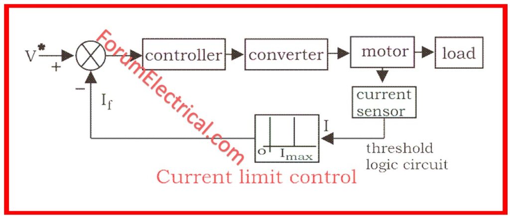
If the current becomes normal, the feedback loop is not active anymore.
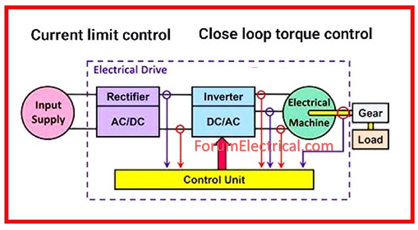
Closed-Loop Torque Control
Such types of loop are applied in
- Battery powered vehicles,
- Rails, and
- Electric trains.
Bluetooth has the reference torque T* according to the accelerator and this T* paves through the loop controller and the motor.
It is the pressure applied on the accelerator that governs the speed of the drive.
Closed-Loop Speed Control
The system applied the inner control loop within the outer speed loop.
The inner control loop regulates the amount of ‘motor current’ the motor should take and the amount of ‘motor torque’ below a safe limit.
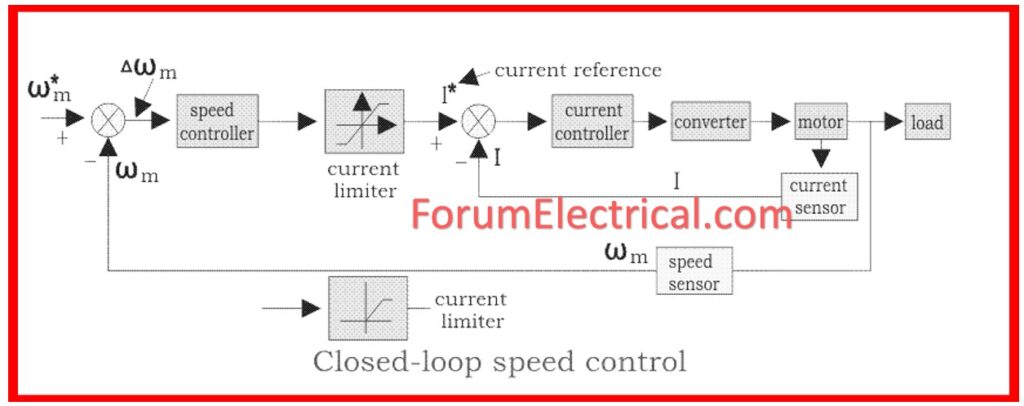
Let there be a speeds ω*m which will give a positive error on the order of Δ ω*m.
The speed error is again fed to a speed controller connected to a current limiter, which is overloaded even when there is a small error in speed.
- The current value of the limiter for the inner current control loop sets current.
- Next, the drive increases its speed and when the speed of the drive becomes equal to the reference speed the motor torque is only equal to the load torque.
- This decreases the reference speed and forms a negative speed error.
- When the current limiter saturates then the drive becomes de-accelerate in the braking mode.
- When the current limiter gets fully saturated it gets switched from deceleration to acceleration mode.
- Thus there arises the need to design a closed-loop speed control of Multi Motor Drives.
- In such a type of drive, the load is divided among the different motors/engines that are incorporated in the system.
- In this system, the most common type of motor is distributed with most of each section’s load.
The above mentioned shows that the rating of the motor is different for the different types of load but all the motors are running at the same speed.
However, the assigned torque demand of each motor should be met by its own driving motor; then the driving shaft has to bear only small synchronizing torque.
In locomotives, due to the difference in the amount of wear and tear, which shapes the wheel alters the motion – the wheel of the locomotive rotates at a different speed.
Thus, the vehicle driving speed also varies.
In addition to this, the torques must also be split half way between the various motors; if they are not, then one of the motors is overworked while the other is hardly working at all.
Therefore, the rated locomotive torque will not reach the sum of the individual motor torque rating.
Closed Loop Control of Speed of a DC Motor
- Brush DC motors and
- Brushless DC motors
are mostly used in open-loop, that is, a voltage is applied to produce a desired speed.
However, when the load is applied the rotational speed will slow down in reference to the specific speed-torque characteristic of the motor.
Most applications do not present a problem with this natural decrease like a personal drill or an electric screwdriver.
However, if the application is somewhat more complex, like a peristaltic pump or certain types of surgical equipment, the requirements grow considerably – it is essential not only to maintain the speed at a very stable level but also to have a very precise control over the motor speed.
To sustain this speed in DC motors at the required value, a controller containing the closed loop speed control can be used and the utilization of closed loop speed control in DC motors.
Speed Torque Characteristic of DC Motors
A DC motor will have a special speed torque relation that implies that at any given voltage the motor will turn at a certain speed which will be slower when more torque is applied.
The speed varies directly with the voltage that is cutting the voltage in half and doubles the speed.
We can attain this characteristic curve when determining the no-load speed and the stall torque of a motor pertaining to a given voltage.
The motor will turn at the No-Load Speed, which is given in the following formula (rotational losses wasn’t taken into account), if no torque is applied:
No Load Speed (rad/s) = Voltage (V) / Torque Constant (Nm/A)
The motor maximum torque that can produce at a given voltage is known as the stall torque, and it is determined by using the following formula to stop the motor:
Stall Torque Formula (Nm) = [Voltage (V) x Torque Constant (Nm/A)]/Coil Resistor (Ω)
Open Loop Speed Control of DC Motor
In many applications, just a basic control of the DC motors is needed in order to get the needed motion, and the final stage of this movement control is usually accomplished by creating the required cycle of voltages; the speed is not checked in this case and the motor should progress appropriately by its ST characteristics. This is called an open loop.
In an open loop, if the load increases, it will result in the decrease of speed of the motor.
Ex: Use of a personal drill, whereby the speed of the drill slows down as it becomes nearly hard to drill (high ML).
However, this way to drive a motor is suitable for several applications, employing a more powerful motor or using a gearbox enables to decrease the speed loss.
However, this phenomenon will be a subject to occurrence and can become an issue in critical applications.
Closed Loop Speed Control of DC Motor
In certain cases, it is necessary to keep the speed at a constant (or) give the maximum power as the load torque is rising.
In these cases it may be appropriate to have a controller, which will have a speed control function in the closed loop.
This is such a controller will continually assess the actual speed of the motor, as
The controller will then compare this speed to the reference and readjust the voltage or current to keep a constant speed to the speed command.
The voltage and current on the average are restricted (thermally or dependent on the supply source) for a given function and as a result boundaries in respect to speed together with torque are predetermined by this nature of the motor.
Important points to consider:
In this case, ωref is the reference speed created by the command and pursued by the controller.
Thus, by controlling the speed from Point A to Point B, the stability of the speed within the reference speed ωref is achieved.
If the load increases beyond the value in Point B, as in Point C, the motor will, for all practical purposes, be operated in a voltage controlled mode; that is the speed will decrease according to the speed-torque characteristic of the motor at the maximum voltage. This is equivalent to ωavail, the maximum available speed.
If the load is more than the maximum torque value, Tmax in Point D the motor will stop.
Using the following formula, the maximum torque is determined based on the motor’s torque constant and the maximum current available, or, Imax:
Tmax = Torque Constant (mNm) x Imax (A)
Note
A small difference between the targeted speed and the read speed will be maintained and it is necessary to check that the obtained error value is admissible. This is referred to as the residual deviations.