
- What is High Pass Filter?
- What is Low Pass Filter?
- High Pass Filter vs Low Pass Filter
- Types of High Pass Filters
- Active High Pass Filter Vs Passive High Pass Filter
- Equation for HPF-High Pass Filter Transfer Function
- Cut-off Frequency High Pass Filter
- Bode Plot (or) Frequency Response for a High Pass Filter
- Magnitude Plot
- Phase Plot
- Ideal High Pass Filter
- Applications of the High Pass Filters
- What sort of filter does a Bode plot employ?
- What is the transfer function of the high pass filter?
- What is the correct method to plot the high pass filter?
The term “filter” indicates that it will eliminate inappropriate elements. A water filter is the ideal illustration of a filter. Why is it employed? It is employed to purify water of contaminants. The electric filter operates in an identical way as a water filter.
- Amplifiers,
- Inductors,
- Capacitors, and
- Resistors
are components of the electric filter. The electric filter is employed to attenuate signals that are lower or higher in frequency while allowing signals at certain ranges of frequency to flow through it.
Cut-off frequency refers to the frequency during which a filter works. The filter’s cut-off frequency is chosen during filter design.
What is High Pass Filter?
A high pass filter (which is also referred to as a low-cut filter (or) bass-cut filter) is an electrical filter that allows sounds with frequencies more than a specified cut-off frequency while attenuating signals with frequencies less than that cut-off frequency.
What is Low Pass Filter?
A low-pass filter is the inverse of the high-pass filter in that it permits signals with frequencies less than the cut-off frequency but rejects any signals with frequencies higher than the cut-off frequency.
Band pass filters combine high pass and low pass filters to restrict sound to a particular frequency range.
High Pass Filter vs Low Pass Filter
| High Pass Filter – HPF | Low Pass Filter – LPF |
| An electronic filter called an HPF accepts signals with frequencies higher than the cut-off frequency. The filter is called as low-cut filter. | An electric filter called an LPF enables signals with frequencies below the cut-off frequency. It is also called as a high-cut filter. |
| The capacitor is followed by the resistor in HPF. | In LPF, the capacitor follows the resistor. |
| Frequency is higher than the cut-off frequency. | Frequency is Lower compared to the cut-off frequency. |
| It is essential to remove low-frequency disturbance from the signal input. | It is essential to eliminate the aliasing effect. |
| It is utilised in amplifiers such as audio amplifiers and amplifiers with minimal noise. | In communication circuits, it functions as an anti-aliasing filter. |
Types of High Pass Filters
Depending on the circuit architecture and the components used to create a filter, there are several types of high-pass filters. The different high-pass filter types consist of:
1). Passive High Pass Filter
2). Active High Pass Filter
3). RC High Pass Filter
4). First Order High Pass Filter
5). Second Order High Pass Filter
6). Butterworth High Pass Filter
7). Chebyshev High Pass Filter
8). Bessel Filter
1). Passive High Pass Filter
Only passive components like resistors, inductors, and capacitors make up the passive filter. It won’t make use of any additional power supplies or amplifiers.
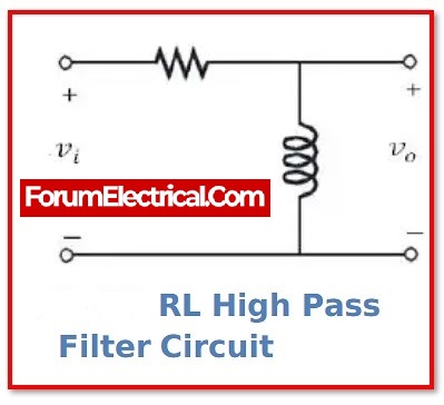
A resistor & capacitor (RC) (or) resistor & inductor (RL) combination makes up a passive high pass filter.
2). Active High Pass Filter
The operational amplifier (OP-AMP) or amplifier with gain control is part of the active filter, which also combines a passive filter.
It is created by coupling an OP-AMP component that is either inverting or non-inverting with a passive filter.
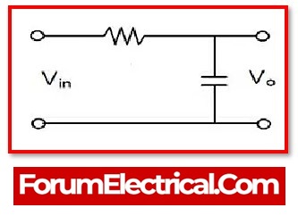
3). RC High Pass Filter
Because it merely has a capacitor connected in series with a resistor, the RC filters is one form of passive filter.
However switch out the capacitor & resistor in the circuit design to create a high pass or low pass filter.
For the signal with a frequency of lower than the cut-off frequency, the capacitor delivers extremely strong reactance. The capacitor serves as an open switch in this condition.
For signals with frequencies greater than the cut-off frequency, the capacitor delivers low reactance. The capacitor serves as a close switch in this condition.
4). First Order High Pass Filter
First Class A high pass filter is made up of only one capacitor (or) inductor. This type of filter is called as first-order transfer function.
It indicates that if derive an equation in the s-domain, the greatest power of’s’ is one. This is only conceivable if just one energy storage device, such as an inductor and a capacitor, is used.
Depending on the components used, the first order filter might be active or passive. It may be a first-order filter if it only employs active components. A first-order passive high pass filter is an RC high pass filter.
5). Second Order High Pass Filter
Cascade two first-order high pass filters to obtain a second-order high pass filter. As a result, it has two reactive components & is a second-order circuit.
The key difference between first and second order filter slopes is the stop band. The second-order filter has twice the slop of the first-order filter.
Ex:The slop of a first-order Butterworth filter is +20 db/decade, while the slop of a second-order Butterworth filter is +40 db/decade.
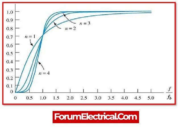
6). Butterworth High Pass Filter
In the pass band, the Butterworth filter is intended to have a uniform flat frequency response. As a result, there is no frequency response ripple in the pass band.
7). Chebyshev High Pass Filter
The Chebyshev filter minimises the error between the real and ideal filters in all filter ranges. Filters are classified into two types:
- Type I and
- Type II.
The type-I filter is referred to as the “Chebyshev Filter,” while
the type-II filter is referred to as the “Inverse Chebyshev Filter.”
This filter response is the best compromise between ripple & slope. The filter response is identical as the Butterworth Filter when the ripple is set to 0%. However, a ripple of 0.5% is a perfect choice for the digital filters that produce crisp slop.
The filter is known as a type-I Chebyshev Filter if the ripple is present in the pass band, and a type-II Inverse Chebyshev Filter if the ripple is present in the stop band.
The pass band & stop band shift quickly. However, in this case, the ripple will be present in both the pass and stop bands. Elliptical Filter is the name given to this sort of filter.
8). Bessel Filter
The Butterworth filter performs well in terms of transient and amplitude behaviour. The Chebyshev filter offers a better amplitude response than the Butterworth filter but suffers from transient behaviour.
The transient responsiveness of the Bessel filter is excellent. However, the amplitude behaviour is subpar. The Bessel filter is intended to provide a continuous group delay in the pass band.
Active High Pass Filter Vs Passive High Pass Filter
| Active-High Pass Filter | Passive-High Pass Filter |
| Active Filter is characterised by its use of active components such as OP-AMP and Transistor. | The term “passive” refers to the components of the filter, such as the capacitor and inductor. |
| It requires an additional source of electricity. | It runs on the signal input & does not need an additional power source to function. |
| It is restricted in terms of frequency. | It does not have any frequency restrictions. |
| Higher in cost. | Lower in cost. |
| Stability that is below average. | Better stability. |
| The Weight is Very Low. | The Weight is Very high due to the reason that the inductor itself has a very high weight. |
| Sensitivity is more. | Sensitivity is low. |
| Q Factor is high. | Q Factor is low. |
| Efficiency is high. | Efficiency is low. |
| It necessitates a complicated control system. As a result, the structure of the filter is complex. | It is simple to design. |
| Strong Frequency Response Characteristics. | There is a lack of sharpness to the frequency response characteristic. |
Equation for HPF-High Pass Filter Transfer Function
The transfer function represents filters mathematically. This mathematical statement describes the filter’s input-to-output characteristics .
The transfer function of the first order high pass filter is calculated using the formulae below.
ZR=R & ZC=1/sC
Output Impedance equals:
Zout=ZR
Input Impedance equals:
Zin=ZR+ZC
The transfer function is referred to as the output voltage divided by the input voltage.
Vout/Vin = Zout/Zin
By solving the equation can get,
Vout/Vin= R/[R+(1/Sc)]
T(s) = s/[s+(1/RC)]
The standard transfer function is written as follows:
T(s) = a1s/[s+ω0]
Where,
a1– Amplitude of Signal
ω0– Angular Cut Off Frequency
Based on the information provided by this transfer function for the higher frequency
T(s- ∞) =a1
Transfer function for the lower frequency
T(s- 0) = 0
As a result, it shows a maximum magnitude for the higher frequency and zero magnitude for lower frequency.
ω0 = 2Πf0 = 1/RC
Cut off frequency f0 = 1/2ΠRC
Cut-off Frequency High Pass Filter
The frequency that establishes the boundary between the pass band & stop band is known as the cut-off frequency.
Fc = 1/2ΠRC
If the signal frequency for a high pass filter is higher than the cut-off frequency, the signal will be allowed to pass through. Additionally, the signal will be attenuated if its frequency is lower than the cut-off frequency.
Fc = 1/2Π√R1C1R2C2
When developing a filter, the user determines the cut-off frequency. The equation below is how it is stated for the first-order RC high pass filter. This formula applies to both high pass and low pass filters.
Fc = 1/2ΠR1C1
Bode Plot (or) Frequency Response for a High Pass Filter
When compared with the frequency response of low pass filter, the frequency response of the high pass filter, as shown by it bode plot, is exactly the opposite.
A plot of the frequency response of filter circuit may be generated by using the transfer function.
The magnitude of transfer function may be used to determine the magnitude curve.
│H(jω) │= ω / √ [ω2 + (1/RC)2]
The transfer function’s phase equation may be used to determine the phase curve.
q( jω) = 900 – tan-1(ωRC)
Magnitude Plot
The magnitude curve shows that it will reduce the low frequency at a slope of +20 db/decade. The stop band is the area between a beginning point and the cut-off frequency.
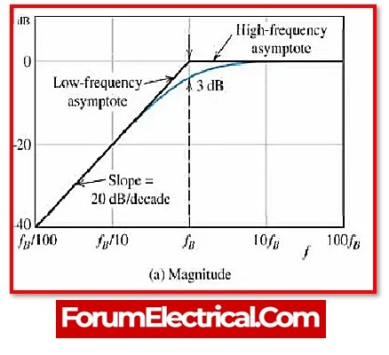
It allows the signal to pass when it passes the cut-off frequency. A pass band is the area above the cut-off frequency point.
The output voltage amplitude is the 70.7% of the input voltage at the cut-off frequency point.
Phase Plot
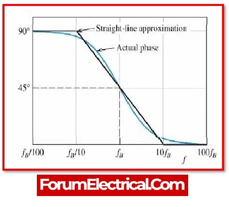
The phase angle of output signal at the cut-off frequency is +45 degrees. The phase map of the filter’s output response indicates that it may pass to infinite frequency. In application, however, the output response does not obtain infinity.
The frequency range of the filter is restricted by correct component selection.
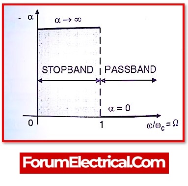
Ideal High Pass Filter
The ideal high pass filter eliminates all signals with frequencies less than the cut-off frequency. It will be necessary to make a rapid transition between the pass band and the stop band.
For signals with a frequency greater than the cut-off frequency, the amplitude will stay unchanged. And the amplitude will be entirely zero for signals with frequencies lower than the cut-off frequency. As a result, the magnitude characteristic of an ideal high pass filter is flat.
The ideal high pass filter’s transfer function is given in the formula below:
│H(ω) │= 1 │ω │>ωc
│H(ω) │= 0│ω │<ωc
For practical filters, this type of perfect high pass filter characteristic is not feasible. The Butterworth filter characteristic, on the other end, is very near to the ideal filter.
Applications of the High Pass Filters
High pass filters are used for a variety of purposes, including:
- It is used to minimise low-frequency noise in amplifiers, equalisers, and speakers.
- High pass filters are employed in image processing to sharpen the picture.
- It’s employed in a variety of control systems.
What sort of filter does a Bode plot employ?
One method for illustrating the size & phase of a transfer function for any of those circuits is using a Bode plot. In certain circuits, a bandpass filter will begin to resemble a low-pass or high-pass filter, and a Bode plot may show this characteristic.
What is the transfer function of the high pass filter?
Lower frequency electrical impulses are severely attenuated by a high-pass filter, which still allows virtually entire transmission of high frequency electrical signals.
What is the correct method to plot the high pass filter?
The frequency response of the high pass filter, also known as the bode plot, is exactly opposite to that of the bode plot of low pass filter. It is able to depict the frequency response of the filter circuit by using either its transfer function or its frequency response function.