
What is a Servo Motor?
A servo motor is an electric motor that can accurately control its angular or linear location, speed, and torque.
- What is a Servo Motor?
- What does a Servo Controller do?
- How to Communicate a Servo Drive Controller with a PLC?
- Step-by-Step Procedure
- Step-1: Determine the Communication Protocol
- Step-2: Hardware Setup
- Step-3: Add the Servo Drive to the PLC Configuration
- Step-4: Configure PROFINET Communication
- Step-5: Map I/O Signals
- Step-6: Write PLC Code for Control
- Step-7: Test and Commission
- Step-8: Fine-Tuning
It consists of an appropriate motor connected to a sensor for position feedback & a controller that governs the motor’s movement in accordance with a predetermined set point.
The phrase servo derives from the Latin word servus, which means servant or slave. This reflects the earlier application of servo motors as auxiliary drives to supplement the primary drive system.
A servo motor is an electric motor that changes position, speed, (or) torque in response to controller inputs.
Servo motors are used in industries such as
- Robotics,
- CNC machinery, &
- Automated production
because of their precision, quick response, and fluid motion.
What does a Servo Controller do?
The servo controller connects the servo motor to a higher-level control system (PLC or programmable logic controller). It adjusts the original signal & sends it to the motor.
PLC: Programmable Logic Controllers (PLCs) & servo motors are essential components of modern industrial automation systems.
PLCs are specialized digital computers that manage and automate industrial activities including managing machinery on factory assembly lines, controlling production equipment, and assuring the smooth operation of complicated systems.
They accept inputs from various sensors & switches, interpret the data using pre-programmed instructions, and deliver control signals to actuators such as motors.
Servo Drives: On the other end, servo drives are necessary for controlling servo motors.
They analyze PLC instruction signals to precisely regulate the motor’s speed, position, and torque.
This fine control is essential for applications that require precise motion & positioning, such as robotics, CNC machines, and automated manufacturing lines. By combining PLCs and servo drives, industries can improve efficiency, accuracy, and production, resulting in more dependable and complex automation solutions.
The controller therefore allows for extremely fine control of position, speed, and torque.
How to Communicate a Servo Drive Controller with a PLC?
Step-by-Step Procedure
PLC Used: Siemens S7-1500 PLC
Step-1: Determine the Communication Protocol
Identify the communication protocol supported by both the Siemens S7-1500 PLC and the Servo Drive (e.g., PROFINET, PROFIBUS, or Ethernet/IP).
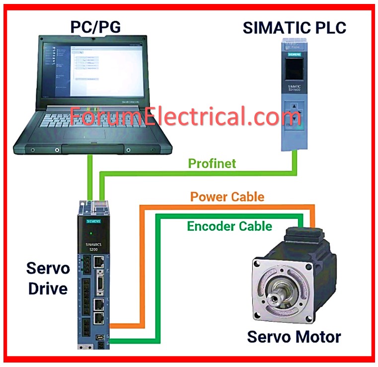
Step-2: Hardware Setup
Connect the servo drive to the Siemens PLC.
A PROFINET or another communication network that is compatible should be used to make sure that the required physical connections are created.
Step-3: Add the Servo Drive to the PLC Configuration
Open TIA Portal, and in the hardware configuration, add the servo drive to the hardware list.
If the specific servo drive is not available in the library, download the GSD file from the manufacturer’s website and import it into the TIA Portal hardware catalog.
Step-4: Configure PROFINET Communication
Assign IP addresses to both the PLC and the Servo Drive. Ensure that both devices are on the same network.
In the TIA Portal, configure the PROFINET connection and assign the correct device to the configured network.
Step-5: Map I/O Signals
Map the input/output signals of the servo drive. These signals will be used to control and monitor the servo motor (e.g., speed, position, torque).
Define the control & status word data points that are required in order to guarantee that the servo drive and the PLC are able to communicate effectively with one another.
Step-6: Write PLC Code for Control
Write the PLC program to control the servo drive. Develop a program that responds to standard commands like start, stop, speed control, & positioning using the TIA Portal.
Use instructions like Speed Control (or) Position Control depending on the type of control needed.
Here’s an example of PLC code that controls a servo drive using Ethernet/IP connectivity. This code is written in ladder logic, which is commonly used in PLCs like Allen-Bradley or Siemens. It is assumed that the servo drive is controlled in velocity mode & that you are giving commands to the drive such as start, stop, and speed.
Servo Control using Ethernet/IP (Example: Ladder Logic)
Components
The servo drive is controlled via Ethernet/IP.
PLC manufacturers include Allen-Bradley, Siemens, and others.
Inputs/Outputs
Start Command: A button or input that activates the servo.
Stop Command: A button or input that stops the servo.
Speed Reference: A numeric input or variable used to govern speed.
Tags/Variables
Servo_Start (BOOL): Starts the servo.
Servo_Stop (BOOL): Stops the servo.
Servo_Speed (REAL): Speed reference (RPM/units per second).
Servo_Status (BOOL): Indicates if the servo is running.
Servo_Error (BOOL): Indicates whether the servo is faulty.
Servo_IP_Address: Servo_IP_Address is the servo drive’s IP address for Ethernet/IP connection.
Step 1: Command Logic to Start & Stop Servo
| Command | Logic | Instruction | Description |
| Servo Start | [XIC] | Servo_Start_Cmd | Start the servo |
| Servo Stop | [XIO] | Servo_Stop_Cmd | Stop the servo |
| Error Reset | [XIC] | Servo_Reset_Cmd | Reset any fault |
| Servo_Start (BOOL) | Servo_Stop (BOOL) | Network 1: |
|---|---|---|
| [ ] Push_Button_Start | [ ] Push_Button_Stop | Inputs (e.g., HMI or Physical Buttons) |
| [XIC Push_Button_Start]—-(OTE Servo_Start) | Set Servo_Start when Start Button is pressed | |
| [XIC Push_Button_Stop]—-(OTL Servo_Stop) | Set Servo_Stop when Stop Button is pressed |
|—-[ I0.0 ]—–[ %QW100 ]—-[ %MD104 ]—-|
| Start Button Control Word Speed Setpoint |
|---|
We set the Servo_Start bit as the “Start” button is hit, and reset it when the “Stop” button is pressed.
Step 2: Set Speed Reference
| Input | Instruction | Description |
| Speed Input (REAL) | MOV Speed_Input Servo_Speed | Move the HMI/Operator input to the servo speed tag |
| Servo_Start (BOOL) | Network 1: |
|---|---|
| [ ] Speed_Input | Input for speed reference (e.g., from HMI) |
| [MOV Speed_Input Servo_Speed] | Move the input speed value to the Servo_Speed tag |
|—-[ I0.0 ]—–[ MOVE ]———————|
| Start Button Source: %MW50 Destination: %MD104 |
|---|
This rung transfers the input speed value from the operator interface (HMI) or another source to the Servo_Speed tag, which is then transmitted to the servo drive.
Step 3: Communication with the Servo Drive
Servo Control Function Block (Ethernet/IP Command Examples)
Assuming that the servo drive supports Ethernet/IP connectivity, you can use function blocks in PLC programming software.
| Servo_Start (BOOL) | Servo_Stop (BOOL) | Servo_Speed (REAL) | Servo_Status (BOOL) | Servo_Error (BOOL) |
|---|---|---|---|---|
| Ethernet/IP Function Block: Command Start/Stop and Set Speed Reference | ||||
| Send Start/Stop commands and Speed to Servo via Ethernet/IP communication | ||||
| [MSG Instruction] or [COMM Function Block] | Setup as Ethernet/IP communication to send | |||
| the control command and speed to the servo |
|—-[ I0.1 ]—–[ %QW100 ]——————-|
| Stop Button Reset Control Word |
|---|
The MSG instruction (or similar communication block, depending on the PLC) is used to deliver the start/stop command & speed reference to the servo drive over Ethernet/IP.
Servo Start: When Servo_Start is triggered, the PLC sends the start command to the servo motor.
Servo Stop: When Servo_Stop is triggered, the PLC issues a stop command.
Speed Reference: The servo receives the speed value from Servo_Speed.
Step 4: Monitor Servo Status & Errors
| eedback Type | Instruction | Description |
| Servo Running Status | XIC Servo_Status_FB | Feedback: Servo is running or not |
| Servo Error Feedback | XIC Servo_Error_FB | Feedback: Servo has encountered a fault |
| Current Position | MOV Servo_Position_FB Current_Position | Move the servo position feedback to a tag |
| Servo_Status (BOOL) | Servo_Error (BOOL) |
|---|---|
| [XIC Servo_Status_FB]—-(OTE Servo_Status) | Monitor running status from the servo |
| [XIC Servo_Error_FB]—–[OTE Servo_Error] | Monitor fault status from the servo |
|—-[ %IW100.0 ]—————–( )————|
| Ready Signal |
|---|
This rung tracks the Servo_Status & Servo_Error feedback signals. When the servo is in operation, the Servo_Status_FB feedback bit is set. Similarly, if a problem occurs, the Servo_Error_FB feedback bit will be activated.
Example PLC Programming
| Servo Control Logic: Network 1 |
| [XIC Push_Button_Start]—-(OTE Servo_Start_Cmd) | Send start command
| [XIC Push_Button_Stop]—-(OTE Servo_Stop_Cmd) | Send stop command
| [XIC Reset_Button]——–(OTE Servo_Reset_Cmd) | Send reset command (clear faults)
| Speed Reference Logic: Network 2 |
| [MOV Speed_Input Servo_Speed] | Move speed input value to Servo_Speed tag
| Feedback Monitoring: Network 3 |
| [XIC Servo_Status_FB]—-(OTE Servo_Running) | Monitor running status
| [XIC Servo_Error_FB]—–[OTE Servo_Error] | Monitor error status
| [MOV Servo_Position_FB Current_Position] | Move position feedback to Current_Position tag
Step-7: Test and Commission
Download the program to the Siemens S7-1500 PLC.
Test the communication and operation of the servo drive with the PLC. Adjust parameters as necessary to achieve smooth operation.
In order to monitor any defects or communication failures, you should make sure that error handling is appropriately established.
Step-8: Fine-Tuning
Adjust the control parameters like
- Acceleration,
- Deceleration, and
- Torque limits
based on the application’s requirements.
In order to verify the final configuration, the servo motor should be operated under real-time conditions.