
A programmable logic controller (PLC) manages manufacturing operations for integrated production lines & equipment.
With the development of programmable logic controllers (PLCs), the need for an immense number of relays or timers in facilities that have multiple inputs & outputs was eliminated.
Because of its endurance and capacity to automate various operations, PLCs have become a modern manufacturing staple.
In this post, we will look at the basic architecture of programmable logic controllers (PLC).
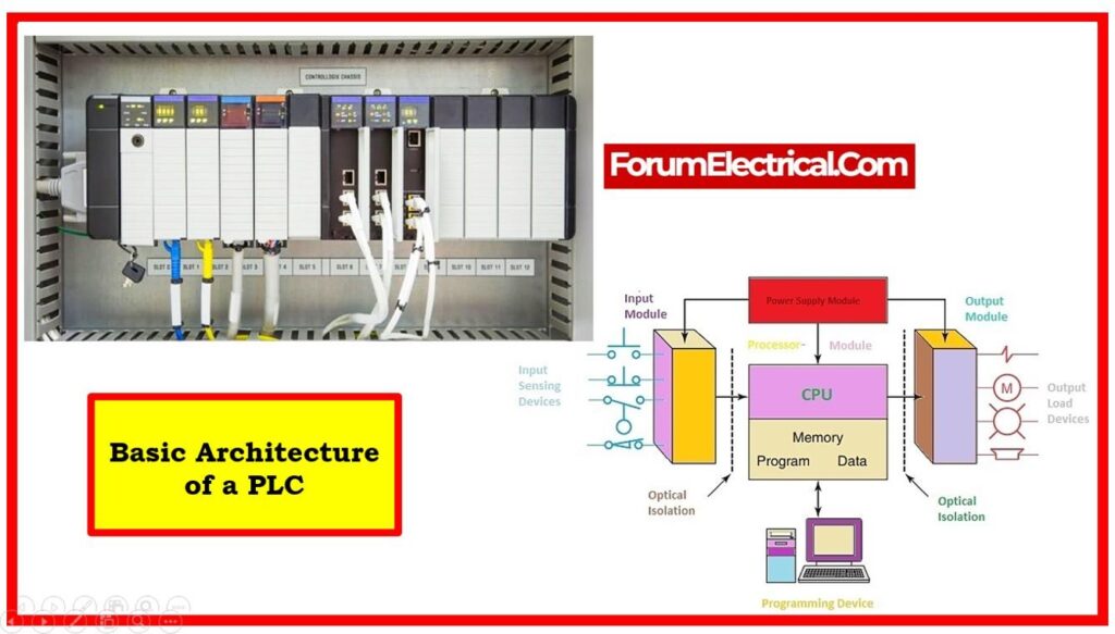
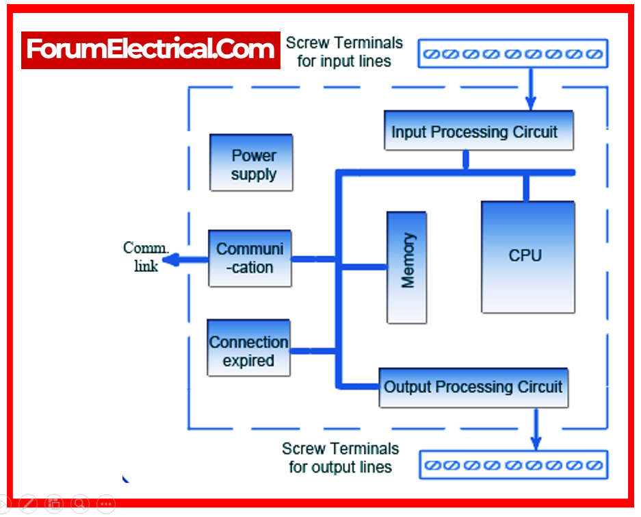
PLC Structure
PLC structure, which includes a
- CPU,
- Memory sections, and
- Circuitry for receiving and outputting data.
A PLC can be viewed as a box containing hundreds of thousands of individual relays, counters, timers, & data storage locations.
These counters, timers, and so on do not exist physically, but are simulated and can be referred to as software counters, timers, and so on.
The internal relays are emulated using bit positions in registers.
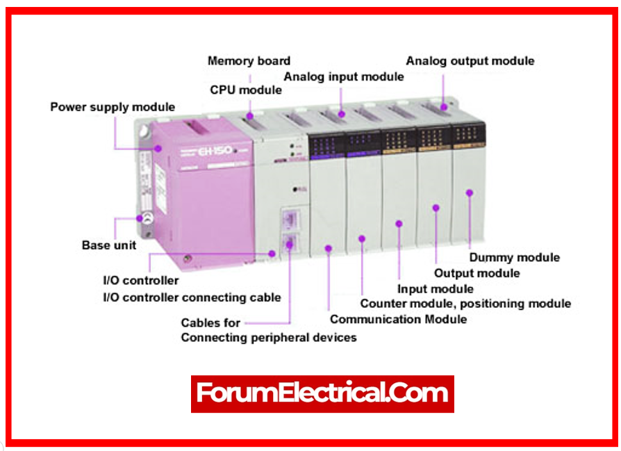
Hardware
A PLC’s major components are
- CPU
- I/O Modules
- Power Supply
- Memory Areas
- Input Relays
- Internal Utility Relay
- Counters
- Timers
- Output Relay
- Data Storage
CPU
- The CPU is the PLC’s brain, responsible for carrying out certain operations.
- These actions or outputs are carried out based on signals & data received from associated inputs.
- The CPU executes control programs, processes input signals, and produces output signals according on program logic.
I/O Modules
- PLC input modules connect external devices, such as sensors, switches, & push buttons, to the PLC, allowing it to read digital and analog data like temperature, pressure, flow, and speed.
- Output modules transform CPU signals into digital (or) analog values that are then used to operate output devices.
Power Supply
- The power supply powers the PLC by converting accessible incoming AC power into the DC power needed for the CPU & I/O modules to function effectively.
Memory Areas
- PLCs contain a variety of memory locations for storing program instructions, data, & other information. These memory areas include the following:
- Program memory is where the control program written by the user is stored.
- Data memory stores data values utilized by the control software, such as variables, constants, & I/O statuses.
Input Relays
- These are connections to the outside environment.
- They exist physically and respond to signals from the switches, sensors, and so on.
- Transistors are typically used instead of relays.
Internal Utility Relay
- These do not receive external signals and do not exist in physical form.
- They are simulated relays, and they allow a PLC to neglect external relays. There are also certain relays that are designed to do a single purpose.
- Some are always on and some are always off. Some are only turned on once during power-on & are often used to initialize previously stored data.
Counters
- Again, they do not exist physically. They are virtual counters that can be set to count pulses.
- These counters are typically either up-counting, down-counting, or both.
- Because they are simulated, their counting speed is limited.
- Some manufacturers additionally incorporate high-speed counters that are hardware-based.
Timers
- These do not exist in physical form. They are available in a number of patterns and increments.
- The most popular is the ON-delay form.
- Others include OFF-delay, as well as retentive and non-retentive variants.
- The increments range from 1 ms to 1 sec.
Output Relay
- They have a connection to the external environment.
- They exist in physical form & send ON/OFF signals to solenoids, bulbs, and other components.
- They may comprise transistors, relays, or TRIACS, depending on which type is selected.
Data Storage
- Registers are frequently established primarily for the purpose of storing data.
- They are typically employed as temporary storage for math (or) data.
- They are additionally useful to backup data in the occurrence of a power breakdown.
- These registers make sure that no contents are lost as a result of power outages.
Software
The PLC manufacturer normally chooses the PLC development software.
- Allen Bradley,
- Siemens, and
- GE
each use their own software development platforms to program their PLC models. Once the platform has been selected, the PLC logic is able to be programmed using a wide range of approaches.
The most prevalent PLC programming software’s are
- Ladder logic,
- Function blocks, and
- Structured text.
Ladder Logic
- The most prevalent form of programming is with ladder logic, a graphical PLC programming language.
- Ladder Logic can be used to do operations like as
- Sequencing,
- Counting,
- Timing,
- Data manipulation, and more.
- Ladder logic is constructed similarly to relay logic, except instead of actual switches and coils, the PLC’s memory locations and I/O are used.
- This method is commonly used and similar to classic electrical relay logic diagrams. Ladder Logic displays the control system’s logic as interconnected ladder rungs, each of which has contacts and coils.
Function Block
- Function block PLC programs are expressed as graphical blocks. Signals or data pass into the function block via inputs connected to PLC.
- When incoming signals or data activate the function block’s pre-programmed function, PLC generates one or more outputs.
- Timers,
- Counters,
- Computing min & max values,
- Finding averages, and
- Other typical functions are all available in function blocks.
- Each block has a distinct purpose, such as mathematical computations, logical operations, (or) control functions.
- FBD is commonly employed in sophisticated control systems where modularity & reusability are essential.
Structured Text
- Structured Text (ST) is a text-based programming language for PLCs, equivalent to
- Python,
- Visual Basic, and
- C Language.
- Programming using structured text has several advantages, including having the advantage that the software takes up less space because it is text-based rather than graphic-based.
- Structured text can also be coupled with other programming languages, including by creating function blocks containing structured text functions.
- It supports more complicated programming constructs like loops, conditional expressions, and user-defined functions.
- ST is preferred by programmers with software development experience.
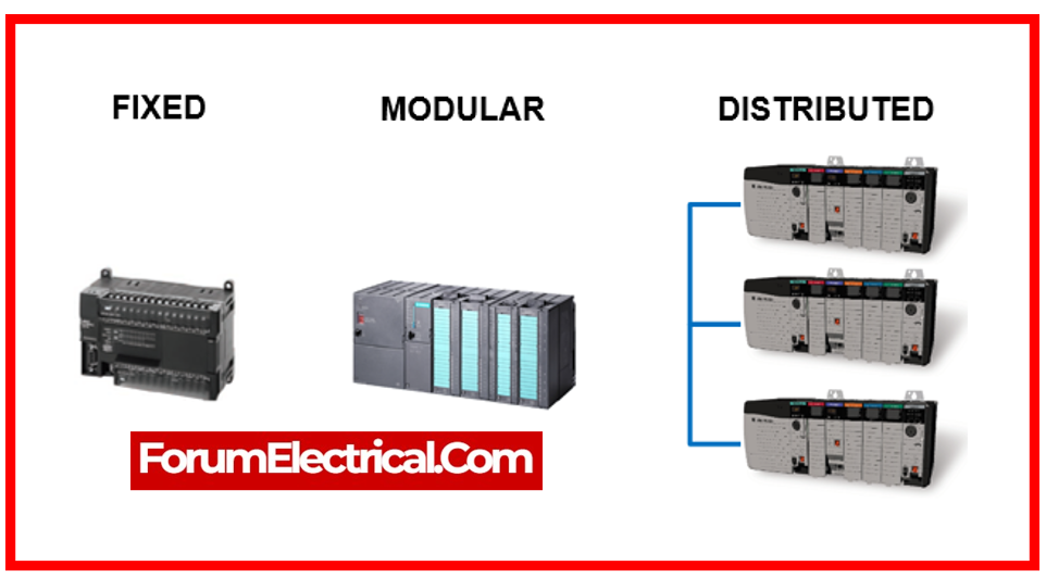
Types of PLC Architecture
There are three main types of PLC architecture accessible for utilization in industrial automation:
- Fixed PLC Architecture,
- Modular PLC Architecture, and
- Distributed PLC Architecture.
The nomenclature used to describe PLC types varies between manufacturers, particularly when discussing fixed PLCs.
There is also cross-over between PLC types, with some fixed-type PLCs having modular characteristics and others having distributed-type features.
Fixed PLC Type Architecture
A fixed PLC uses a single unit architecture, in which all hardware components are integrated into a single unit.
A stationary PLC includes hardware components such as a power supply, CPU, memory, input/output, and communication interfaces.
Manufacturers commonly refer to fixed PLCs as fixed, nano, micro, integrated, small, compact, mini, unitary, basic, standard, and brick.
A few examples of fixed PLC types from different manufacturers, together with the nomenclature they use, are listed below:
- Allen Bradley PLC – Micro
- Siemens PLC – Basic Delta PLC Standard
- Omron PLC – Compact
- Koyo PLC – Brick
Advantages of Fixed PLC
- They are small in size and hence take up little room in an enclosure.
- Quick and simple to install.
- They are inexpensive, making them an attractive option for basic applications.
Disadvantages of Fixed PLC
- Fixed PLCs have limited CPU processing power and memory, making it challenging to do complex tasks.
- The number of input, output, and communication interfaces is fixed, making the system inflexible.
- Only appropriate for basic applications with a few inputs and outputs.
Modular PLC Type Architecture
Each of the hardware components of a modular PLC is housed in its own module.
Each PLC module is connected together via a common mounting method. The mounting mechanism has a limited number of modules that may accommodate.
This implies that a modular PLC can be programmed to be application specialized.
A PLC module is a physical component that performs a specific function based on the design of the PLC system. A modular PLC’s key components are the CPU, power supply, input, output, and communication modules. The architecture of these modules varies by manufacturer and is usually not interchangeable between PLC manufacturers.
Modular PLCs are used to automate industrial applications that require a high-power CPU as well as a large number of input & output devices.
These modular PLC-based systems are typically more complicated in terms of operation, process control, and monitoring.
Manufacturing, food & beverage, mining, and logistics are some of the industries that commonly use modular PLCs.
A few examples of the modular PLC types from various vendors are shown below:
- Siemens PLC S7-300 Series.
- Delta Compact Modular Mid-Range – AS Series
- Koyo Micro Modular PLC, DL205 Series
Advantages of Modular PLC
- Distributed I/O modules can be remotely deployed and connected to modular PLCs via a communication link.
- This allows more inputs and outputs, less cabling, and installation flexibility.
- Modular PLCs improve maintenance over permanent ones. Every hardware component is in a module that can be replaced if broken.
Disadvantages of Modular PLC
- They are larger in size and require up more space in an enclosure than a stationary PLC.
- The mounting system is far more complex than a stationary PLC.
- Higher in cost than a stationary PLC, it may not be cost feasible for smaller applications.
Distributed PLC Type Architecture
A high-end distributed PLC system has modular architecture and can connect hardware components across sites via high-speed communication lines.
Each node, rack, or drop in distributed PLC system has many hardware modules in a mounting system.
Every drop, node, and rack in Distributed PLC system needs a communication module and a PLC processor module with I/O modules or merely I/O modules.
Distributed or remote I/O nodes have a communication module without a PLC processing module and merely I/O modules.
Large factories and processing facilities employ distributed PLCs since they are not location-bound.
High-speed communication networks connect CPUs and distributed I/O to allow hardware parts to be located elsewhere. Site-wide process control is provided via distributed PLCs.
High-performance processors, huge memories, massive I/O volumes, higher-level programming languages, and sophisticated process control duties are the main differences between distributed PLCs & other PLCs.
Large process plants previously used DCS. Modern technology-driven PLCs can handle the tremendous demands of the distributed control system.
Distributed PLC Types examples
- Delta PLC-AH Series
- Koyo Specialized PLC – DL405 series
Advantages of Distributed PLC
- A plant-wide control network with several processors & remote I/O drops.
- High-performance processor.
- Large program & data memory.
- Capable of handling massive amounts of I/O.
- Can perform a huge number of sophisticated process control duties.
- Easy to maintain.
- Save time & money on installation fees.
Disadvantages of Distributed PLC
- Large in size, with a larger installation footprint.
- The mounting system is more complicated than a stationary PLC.
- They are more expensive than other varieties of PLC, hence they may be unsuitable for smaller, less sophisticated applications.
- High-level programming expertise may be necessary.