
Purpose
The purpose of this method is to verify the functionalities of a Metal Enclosed Busbar.
- Purpose
- Equipments Required
- Safety Precautions
- Procedure
- Mechanical Check & Visual Inspection
- Electrical Tests
- Ultrasonic Inspection
- Protective Coating Inspection
- Insulation Resistance Test
- Dielectric Strength Test
- Partial Discharge Test (PD)
- Ampacity Testing (Rated Current Test, Heat Rise Test)
- Hi-POT Test
- Contact Resistance Test
- Corrosion Protection
- Documentation and Recordkeeping
- How do you check and maintain busbars?
- What are the faults of busbar?
- What is bus bar in DB?
- Busbar Calculator
Equipments Required
- Megger
- Digital Multimeter
- Phase Sequence Meter
- DLRO – Digital Low Resistance Ohmmeter
- Hi-Pot Test Set
Safety Precautions
For complete safety instructions and precautions, always refer to the test equipment instruction manual.
Procedure
This approach is applicable to all types of metal enclosed busbar.
Mechanical Check & Visual Inspection
1). Check for physical damage/defects.
2). Check the bus arrangement to ensure that it is consistent with the approved plans.
3). Check the tightness of all bolted connections (torque wrench method).
4). Ensure that all enclosure grounding is properly connected.
5). Check internal compartments for the cleanliness (free of dust and moisture).
6). Check all joints for waterproof seals, including expanding interfaces.
7). Check bus conductor support insulators for imperfections such as cracked insulation and broken porcelain.
8). Check the quality of the paint work (both inside and outside).
9). Ensure that ventilation apertures are not obstructed and that they are screened to prevent insects and rain from entering.
10). Moisture drain holes are located at the bottom of the enclosure.
11). Check anti-condensation heaters put at the suitable locations (Bottom).
Electrical Tests
1). Phasing check & ensure proper phase identification.
2). Check for continuity.
3). Bus Joint Resistance (at 100 A DC)
4). Insulation resistance tests.
5). Hi-pot test (to ground, between phases)
6). Functional test for heaters and thermostats.
7). Measure the heater currents.
Ultrasonic Inspection
1). Internal defect detection, thickness measurement, crack identification, and loose joints.
2). Ultrasonic testing is good at detecting cracks on the surface (or) within the busbar’s material.
3). Early diagnosis of cracks is essential for prevention.
Protective Coating Inspection
1). Inspect the busbars protective coatings for evidence of wear or damage. Protective coatings serve to prevent corrosion and extend the life of the busbars.
2). Repair or replace coatings as needed.
Insulation Resistance Test
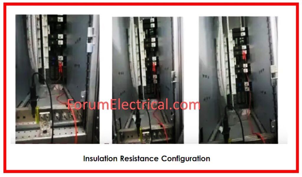
1). The objective of the measurement is to identify the insulation’s leakage current resistance.
2). Insulation tester leads must be connected between the one-phase busbar and the earth. The test voltage shall be selected based on combination & voltage class.
R-E, Y-E, B-E, R-Y, Y-B, B-R
3). Before disconnecting the test leads, the test object must be discharged through the earth. The same.
4). The technique will be followed for the next phases.
5). Insulation resistance values should meet the manufacturer’s minimum. If the value is not attained, the component evaluated must have at least one megaohm for every 1000 V of rated voltage + an additional one megaohm.
Dielectric Strength Test
1). Conduct a dielectric strength test to determine the insulating qualities of the busbars beneath high voltage settings.
2). This test ensures that the insulation can resist the prescribed voltage stress without failure.
Partial Discharge Test (PD)
1). The Partial Discharge test is crucial for determining long-term part performance and discovering inefficiencies in power transfer.
2). This test is especially significant for multilayer laminated bus bars, medium voltage, inverters, and other essential power conductor applications that require superior electrical insulation.
3). The test measures the amount of partial discharge in Coulombs, also known as arcing, across the copper (or) aluminum conductor & the insulation placed to the surface of the bus bar.
4). This arcing can occur if there are small air gaps trapped within the insulating system, or if the conductor’s surface has any defects, or pits.
5). If severe arcing occurs on a regular basis, it can greatly accelerate insulation erosion and result in inefficient power transfer (or) complete collapse of the insulation system.
Ampacity Testing (Rated Current Test, Heat Rise Test)
1). While ampacity tables provide an accurate indication of how a conductor of a certain thickness will react thermally when exposed to a specific quantity of electrical current, a physical test is the only method to ensure that a part will operate as predicted.
2) .This test is carried out by running a particular amperage via the test specimen & detecting the heat rise using thermocouples. This ensures that the part has the appropriate heat rise for its application. The ampacity tables are frequently sufficient for simple bus bars, but parts with more complex geometries or many input/output connections introduce variables that will affect performance calculations.
Hi-POT Test
1). Open the Busbar box & isolate the circuit before testing.
2). Ensure that all equipment (or) cables that will not be examined are separated from the circuit under test.
3). To apply 2-times-plus-two (2X + 2) KV DC of system voltage to the phase under test,
4). For a few minutes, consider the earth.
Note: The real DC high voltage that will be applied is dependent on the state of the busbars.

5). Connect the HIPOT Tester’s ground line to an appropriate building ground or grounding electrode conductor.
6). Connect the high voltage connection to one of the isolated circuit phase’s busbar.
8). After finishing the test, switch the HIPOT Tester from high potential test mode to the Voltage measurement mode to validate that the circuit phase busbar & voltage of the HIPOT. The tester is currently reading 0 voltage.
9). Repeat this test process for every circuit phase busbars, testing each phase to ground. Each phase builds on the previous one.
10). When the testing is done, disconnect the HIPOT Tester from circuits under test.
11). Ensure that the circuits are ready to be reconnected and reenergized.
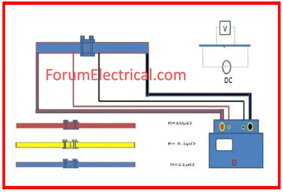
Contact Resistance Test
1). To measure the contact resistance of busbar joints, inject DC current through them.
2). Gradually increase injected DC current to a preset value (e.g., 100A), then take the microohm reading.
Corrosion Protection
1). Apply corrosion protection measures, particularly in environments prone to corrosion. This may include applying corrosion-resistant coatings or using corrosion inhibitors.
Documentation and Recordkeeping
Keep accurate documentation of busbar inspections, tests, & maintenance activities. Documentation helps trace the past of the busbars and assists in future troubleshooting.
Check the test findings against the relevant standards and/or manufacturer’s guidelines.
How do you check and maintain busbars?
Monthly: Clean the busbars, check the connections, and tighten the bolts and screws.
Quarterly: Use thermal imaging cameras to measure insulation resistance & inspect busbar temperature.
Annually: Do a thorough busbar inspection that includes mechanical, electrical, & insulation tests.
What are the faults of busbar?
Bus failures typically occur at joints, connectors, and insulated stand-offs. Bolts loosen, & welded joints fail, often with a hairline crack. Stand-offs break or collapse, but they are also capable of developing tracking if carbon deposits on the surface create a current path.
What is bus bar in DB?
A busbar is a metallic strip or bar (usually copper, brass, or aluminum) that conducts electricity in a switchboard, distribution board (DB), substation (SS), battery bank, (or) other electrical gear. Its primary function is to carry a considerable current of electricity.
