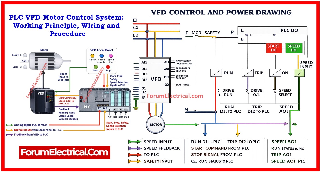
A Variable Frequency Drive (VFD) control system integrated with the Programmable Logic Controller (PLC) and local operator panel provides an accurate speed control, automation & protection for AC motors in industrial applications.
- Core Components
- 1). Variable Frequency Drive (VFD) – The Power Controller
- 2). Programmable Logic Controller (PLC) – The System Controller
- 3). Local Operator Panel – The Human Interface
- Electrical Signal Types used in Control System
- Power Circuit Operation
- Control Circuit and Protection System
- Operational Procedure of PLC-VFD-Motor Control System
- Step-1: Operator Initiates Start Command
- Step-2: PLC receives Input Signal
- Step-3: PLC sends Start Command to VFD
- Step-4: VFD starts Motor
- Step-5: Motor Runs at Required Speed
- Step-6: Feedback sent to PLC
- Advantages of PLC-VFD-Motor Control System
- Applications of PLC-VFD-Motor Control System
- Maintenance Checklist for PLC-VFD-Motor Control System
- Summary
This system enables the operators and automation logic to control the motor speed, monitor performance and also ensure a safe operation using digital, analog and feedback signals.
Such systems are widely used in industries including
• Power plants,
• Substations,
• Manufacturing facilities,
• Water treatment plants and
• HVAC systems.
Core Components
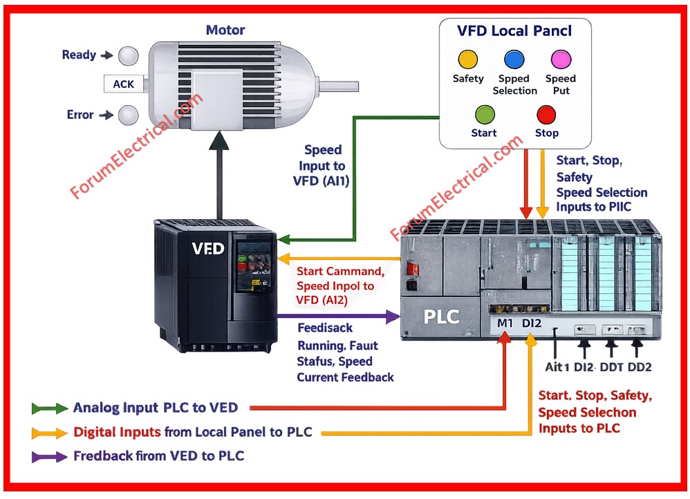
1). Variable Frequency Drive (VFD) – The Power Controller
The Variable Frequency Drive acts as the primary motor controller by converting the fixed frequency AC supply into variable frequency and voltage output.
This allows an accurate control of motor speed and torque.
Primary functions of VFD include:
• Converting the fixed AC supply into DC using a rectifier.
• Converting DC back to the variable frequency AC using an inverter.
• Controlling the motor speed by adjusting the output frequency.
• Providing a motor protection against the overload, overcurrent and faults.
• Sending an operational feedback signal to the PLC.
Key VFD terminals include:
• L1, L2, L3 – Input power supply,
• U, V, W – Output to motor,
• AI – Analog input (speed reference),
• DI – Digital input (start/stop commands),
• AO – Analog output (feedback signal) &
• DO – Digital output (status signals).
2). Programmable Logic Controller (PLC) – The System Controller
The PLC acts as the central control unit responsible for the processing logic, receiving input signals and sending the control commands to the VFD.
Main functions of PLC include:
• Receiving the input signals from the local panel and sensors.
• Processing the control logic based on the programmed (PLC) instructions.
• Sending the start and speed commands to the VFD.
• Monitoring the motor speed, current & fault status.
• Controlling the safety interlocks and also protection systems.
PLC input/output types include:
• Digital Inputs (DI) – Start, Stop & Safety signals.
• Digital Outputs (DO) – Start command to VFD.
• Analog Inputs (AI) – Feedback signals.
• Analog Outputs (AO) – Speed reference signal.
3). Local Operator Panel – The Human Interface
The Local Panel allows the operators to manually control and monitor the motor and their drive system.
Main components of local panel include:
• Start push button,
• Stop push button,
• Speed potentiometer,
• Auto/Manual selector switch &
• Status indication lamps.
Main functions include:
• Manual start and stop control,
• Manual speed adjustment,
• Mode selection between automatic and manual control.
• System monitoring and operation.
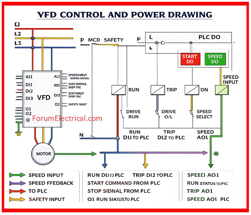
Electrical Signal Types used in Control System
1). Digital Input Signals
The digital signals are used to send ON/OFF commands between the devices.
Examples include:
• Start command from panel to PLC.
• Stop command from panel to PLC.
• Safety interlock signals.
These signals are used to operate at standard control voltages such as 24V DC.
2). Analog Signals
The analog signals are used to control and monitor the motor speed continuously.
Common analog signals include:
• 4-20 mA signal
• 0-10 V signal
These signals represent the motor speed reference and also feedback.
3). Feedback Signals
The feedback signals provide a real time operational status to the PLC.
Examples include:
• Motor running status,
• Motor fault status,
• Motor speed feedback,
• Motor current feedback.
These signals help the PLC to monitor and control system performance.
Power Circuit Operation
The power circuit supplies the electrical energy to the motor through the VFD.
Power flow sequence:
• Three phase AC power is supplied to VFD input terminals (L1, L2, L3).
• VFD converts the AC to DC using a rectifier section.
• DC supply is filtered in the DC link circuit.
• The inverter section converts the DC supply into variable frequency AC.
• Output terminals (U, V, W) supply power to the motor.
This process allows for accurate motor speed control.
Control Circuit and Protection System
The control circuit ensures a safe and reliable operation of the motor.
Main protection components include:
1). Miniature Circuit Breaker (MCB)
The MCB protects the control circuit from:
• Short circuit and
• Overcurrent.
2). Safety Interlocks
Safety interlocks prevent the motor operation during an unsafe conditions such as:
• Emergency stop activation,
• Overload condition and
• Fault condition.
3). Protection Relays
Relays provide protection and feedback signals including:
• Run indication relay,
• Fault indication relay and
• Ready indication relay.
Operational Procedure of PLC-VFD-Motor Control System
The system operates according to the following procedure:
Step-1: Operator Initiates Start Command
The operator presses the start button on the local electrical panel.
Step-2: PLC receives Input Signal
The PLC receives the start signal and verifies the safety conditions including:
• No overload condition,
• No fault condition and
• Safety electrical circuit closed.
Step-3: PLC sends Start Command to VFD
The PLC activates its digital output by sending the start command to the VFD.
Step-4: VFD starts Motor
The VFD gradually increases the frequency and voltage to start the electrical motor smoothly.
This process is called soft starting.
Step-5: Motor Runs at Required Speed
Motor speed is controlled using:
• PLC analog output signal (or)
• Local panel potentiometer
Step-6: Feedback sent to PLC
The VFD continuously sends feedback signals including:
• Motor speed,
• Motor running status,
• Motor current and
• Fault condition.
Advantages of PLC-VFD-Motor Control System
This PLC-VFD-motor control system provides a wide range of advantages which includes:
• Accurate motor speed control,
• Energy savings,
• Smooth motor starting,
• Reduced mechanical stress,
• Improved safety and protection and
• Remote and automatic control capability.
Applications of PLC-VFD-Motor Control System
PLC-VFD-motor control systems are widely used in:
• Power plants,
• Substations,
• Water treatment plants,
• Conveyor systems,
• Pumps and fans,
• HVAC systems and
• Industrial automation.
Maintenance Checklist for PLC-VFD-Motor Control System
The proper maintenance ensures reliable operation.
Maintenance activities which includes:
• Checking the wiring connections,
• Checking the cooling fans,
• Monitoring the fault logs,
• Cleaning the electrical panels,
• Testing the input and output signals &
• Checking the earthing system.
Summary
The PLC-VFD-Motor control system is an essential component in modern industrial automation.
It provides an efficient motor control which improves the system reliability that enhances safety and enables accurate speed regulation.
Proper understanding of system components, wiring, analog/digital signals and operational sequence is essential for the electrical maintenance engineers and automation engineers.

