
Calculator
Understanding transformer fault current is one of the most important calculations in the field of electrical engineering.
Transformer Fault Current Calculator
| Parameter | Calculated Value |
Click here for more Electrical Calculators
If you are designing a new electrical installation, selecting protective devices (or) verifying the safety of an existing system then finding how much fault current a transformer can deliver is essential.
This post explains through the complete calculation process from gathering your input data to interpreting the final results.
What is Transformer Fault Current?
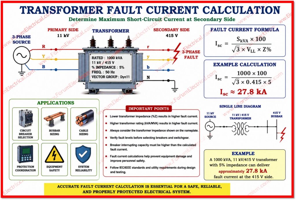
When a short circuit (or) earth fault occurs on the secondary side of a transformer the electrical system attempts to push as much current as possible through the fault path. This is known as the fault current.
The magnitude of that current depends on
- Supply voltage,
- Transformers internal impedance and
- Impedance of the cables connecting the transformer to fault location.
Fault current calculations are essential for 2 reasons.
- They determine the breaking capacity required for fuses, circuit breakers and other protective devices.
- They confirm that protective devices will operate fast enough to disconnect a faulty circuit before damage (or) injury occurs.
Important Terms
Before starting the calculation it is necessary to understand the core parameters involved.
Primary Voltage
Primary Voltage (Vp) is the voltage supplied to the transformers primary winding that is typically from the grid (or) a higher voltage distribution system.
Secondary Voltage
Secondary Voltage (Vs) is the output voltage from the transformers secondary winding which feeds the local installation.
Transformer Rating
Transformer Rating (VA) is the apparent power capacity of the transformer that is expressed in volt-amperes (or) kVA.
Percent Impedance
Percent Impedance (Z%) is the transformers internal impedance expressed as a percentage of its rated voltage.
It represents the percentage of primary voltage that should be applied to drive rated full load current (FLC) through a short circuited secondary winding as per IEC 60909.
Typical values range from 4% to 6% for distribution transformers.
Loop Impedance
Loop Impedance (Zsec) is the total impedance of the earth fault loop which is measured from the transformer secondary terminals through the
- Phase conductor,
- Fault and
- Protective conductor.
How to Calculate the Transformer Fault?
Step-1: Identify the Transformer Configuration
The transformer configuration significantly affects the calculation. There are 3 common types to consider.
1). Single Phase Transformer
For a single phase transformer the secondary voltage & VA rating are utilized directly in the formula without any adjustment.
2). Three Phase Transformer
For a three phase transformer you should divide the secondary voltage by √3 (=1.732) and divide the VA rating by 3 before applying the formula.
This converts the three phase values to single phase equivalent values for the fault loop calculation.
3). Center Tapped Earth (CTE) Transformer
For a center tapped earth (CTE) transformer commonly used in 110V reduced low voltage (RLV) systems on construction sites both the secondary voltage and VA rating are calculated.
Step-2: Calculate the Impedance Voltage (Vz)
The impedance voltage is the actual voltage equivalent of the transformers percent impedance.
It is calculated using the following formula:
Vz = (Vp × Z%) / 100
Example: A primary voltage of 10000 V and a percent impedance of 6%:
Vz = (10000 × 6) / 100 = 600 V
This figure represents how much of the primary voltage is dropped across the transformers internal impedance when full load current (FLC) flows.
Step-3: Calculate Transformer Impedance referred to Secondary
To work on the secondary side of the transformers the internal impedance should be converted (to convert) to the secondary voltage level.
This is done using:
Ztx = (Z% / 100) × (Vseff² / VAeff)
This is the transformers contribution to the fault loop impedance that is referred to the secondary winding.
Step-4: Calculate the Maximum Fault Current
The maximum fault current occurs at the transformer terminals assuming zero external cable impedance as per IEEE C57.
This represents the fault current the transformer can deliver and is used to specify the minimum breaking capacity of protective devices.
Imax = Uo / Ztx
Where
Uo – voltage to earth.
For a line-to-earth fault on a three-phase system,
Uo = Vseff (phase-to-neutral voltage).
It represents the absolute maximum fault current at the secondary terminals.
Step-5: Calculate the Total Loop Impedance (Zsec)
In a installation the fault is never located directly at the transformer terminals.
Cable resistance adds to the total loop impedance.
The full loop impedance formula is:
Zsec = Zp x (Vseff / Vp) + (Z% / 100) x (Vseff² / VAeff) + (R1 + R2)
Where:
Zp – primary circuit impedance (Ze + 2R1) referred to the secondary
R1 + R2 – Resistance of the secondary phase and protective conductors
Step-6: Calculate Actual Fault Current (Ia)
With the total loop impedance known, the actual fault current at the end of the circuit is:
Ia = Uo / Zsec
This is the current that will flow under the actual fault conditions considering for all impedances in the loop.
Protective devices should be capable of operating at this current level within the disconnection time required by the relevant wiring regulations.
Step-7: Calculate the Primary Fault Current (I)
Finally the fault current as seen from the primary side of the transformer that can be found by applying the transformer turns ratio:
I = Ia x (Vseff / Vp)
This is the current that flows in the primary circuit during a secondary fault and it is useful for checking upstream protection coordination.
Practical Considerations
Always use the worst case values that the maximum fault current for device breaking capacity and minimum fault current for checking the protective device operation times.
Cable impedance increases with temperature so that cold state resistance values (at 20°C) typically give the highest fault current while hot state values give the lowest.
Ensure that all the protective devices are rated above the maximum fault current and will operate within the required disconnection time at the actual (minimum) fault current.
Both conditions should be satisfied for the safe and compliant installation.
