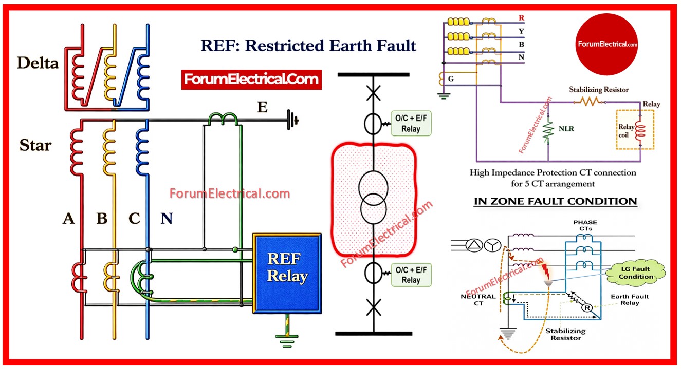
Restricted Earth Fault (REF) protection is a highly sensitive unit protection scheme that is designed specifically to detect internal earth faults within a defined protection zone of a transformer (or) generator.
- What Is REF Protection?
- Working Principle of REF Relay
- Case-1: Normal Condition
- Case-2: External Fault (Outside Zone)
- Case-3: Internal Earth Fault (Inside Zone)
- Protected (Restricted) Zone
- Why REF Protection is important?
- Advantages of Restricted Earth Fault Protection
- Application of REF Protection
- Technical Features of REF Protection
- Difference between REF and Standard Earth Fault Protection
- REF vs Standard Earth Fault Protection
- Types of REF Protection
- 1). High Impedance REF
- 2). Low Impedance REF
- Practical Considerations for REF Implementation
- Important Perspective
- What is 50N and 51N Protection?
Unlike the standard overcurrent (or) earth fault protection REF operates only within a restricted zone typically between the transformer phase CTs and the neutral CT.
Because of this restricted area of operation REF provides:
- Faster response,
- Higher sensitivity,
- Excellent selectivity and
- Improved transformer safety.
REF is widely used in HV and MV substations where the transformer protection reliability is important as per IEC 60255.
What Is REF Protection?
REF protection works on the principle of current balance (Kirchhoff’s Current Law).

Under normal operating conditions:
IR+IY+IB=IN
Where
IR, IY, IB = Phase currents
IN = Neutral current
In normal conditions
The vector sum of phase currents equals the neutral current.
In fault conditions
If an internal earth fault occurs within the protected zone:
- The balance is get disturbed,
- Differential current flows,
- The REF relay use to operates.
Working Principle of REF Relay
Step-by-Step Operation
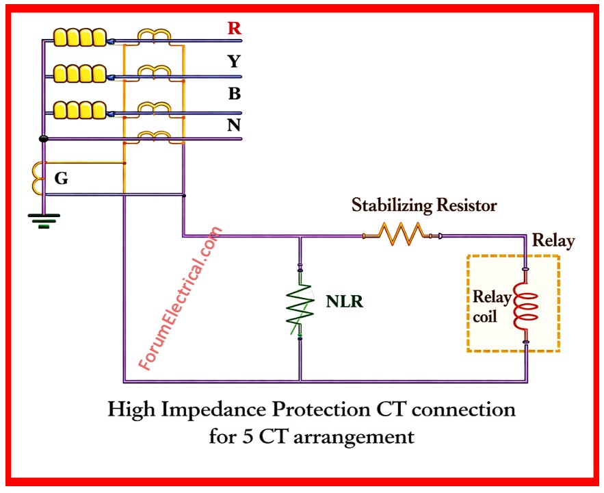
Phase current transformer (CTs) are installed on each phase of the transformer.
A Neutral current transformer (CT) is installed in the neutral grounding connection.
The secondary outputs of phase current transformer (CTs) are connected in residual summation.
The relay compares:
- Sum of phase currents
- Neutral current
Case-1: Normal Condition
Phase current sum = Neutral current
No differential current.
Relay does not operate.
Case-2: External Fault (Outside Zone)
Current transformer (CT) currents remain balanced.
Relay remains stable.
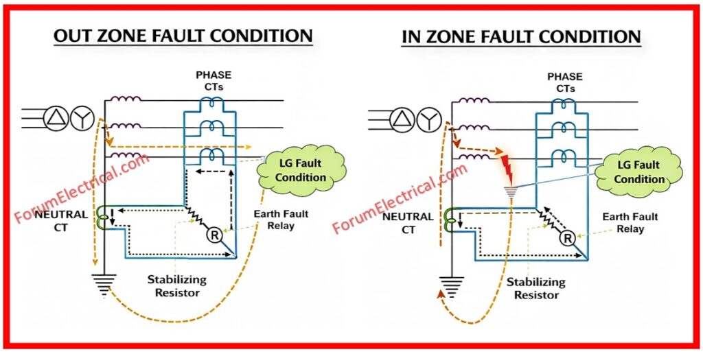
Case-3: Internal Earth Fault (Inside Zone)
Current imbalance occurs.
Differential current flows.
Relay trips the circuit breaker.
Protected (Restricted) Zone
The REF zone is limited between:
- Phase CT locations
- Neutral CT location
Only faults occurring inside this defined zone will operate the REF relay.
This makes REF relay as
- Highly selective,
- Immune to external system faults,
- Stable during through-fault conditions.
Why REF Protection is important?
As per IEEE C37.90, REF provides an additional protection layer beyond the differential protection.
Restricted earth fault protection is important in modern power systems.
It is particularly significant in conditions when accurate fault detection is required.
REF detects even small faults that are restricted to certain zones.
It protects assets such as alternators & transformers by allowing for faster fault clearance, reducing the chance of damage, outages and expensive repair.
Standard earth fault protection devices span large areas. They may be unable to identify minor internal defects in generator windings. This lack of sensitivity may give rise to undetectable adverse effects REF overcomes this through providing accurate, localized protection. This enables early fault detection prior to problems progress into serious equipment failures (or) outages.
Generators & transformers are valuable equipment that must work continuously. The generators restricted earth fault protection ensures that stator windings are monitored specifically. This allows issues to be isolated quickly. It helps to reduce insulation failures while also improving the operational safety & durability of essential equipment.
A restricted earth fault relay detects and isolates faults more quickly. This minimizes the level of adverse effects. It reduces maintenance requirements and eliminates lengthy shutdowns. REF protection assures increased uptime and protection against unexpected maintenance expenditures caused by unmonitored internal failures.
Zone selectivity distinguishes earth faults from confined earth faults. REF concentrates on specific portions whereas earth fault systems have a broad impact. This reduces accidental system tripping and increases protection granularity. It ensures that only the afflicted zone is isolated maintaining the remainder of the system operating.
Advantages of Restricted Earth Fault Protection
- It detects low magnitude internal earth faults.
- It operates very fast (typically < 40 ms).
- It prevents major winding damage.
- It reduces repair and downtime costs.
- It improves system stability.
- It provides backup to the transformer differential protection.
REF is especially effective for detecting:
- Winding insulation failures,
- Partial earth faults,
- Low current internal faults.
Application of REF Protection
REF protection is commonly applied in:
Power Transformers (HV/MV)
- 11 kV / 33 kV transformers
- 33 kV / 110 kV transformers
- Generator stepup transformers
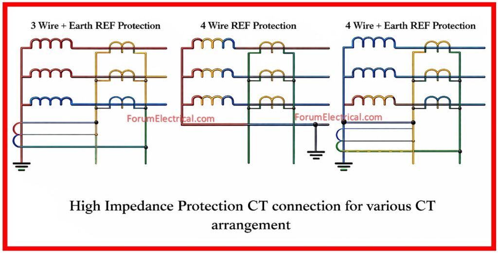
arrangement
Medium Voltage Switchgear
- Incomer panels
- Busbar protection schemes
Grounded Systems
- Solidly grounded neutral systems
- Low resistance grounded systems
Technical Features of REF Protection
CT Arrangement
The Phase CTs connected in residual configuration.
The Neutral CT installed at star point.
Sensitivity
REF operates at approximately 10% of rated current (or) lower.
REF much more sensitive than standard earth fault relay.
Stability
It is stable during external faults.
It requires proper CT matching (ratio & class).
It requires low CT saturation.
Operating Time
REF protection is very fast tripping (< 40 ms typical)
Difference between REF and Standard Earth Fault Protection
REF vs Standard Earth Fault Protection
| Feature | REF Protection | Earth Fault Protection |
| Protection Zone | Restricted | Entire system |
| Sensitivity | Very High | Moderate |
| Selectivity | Excellent | Limited |
| Speed | Very Fast | Slower |
| External Fault Stability | High | Moderate |
Types of REF Protection
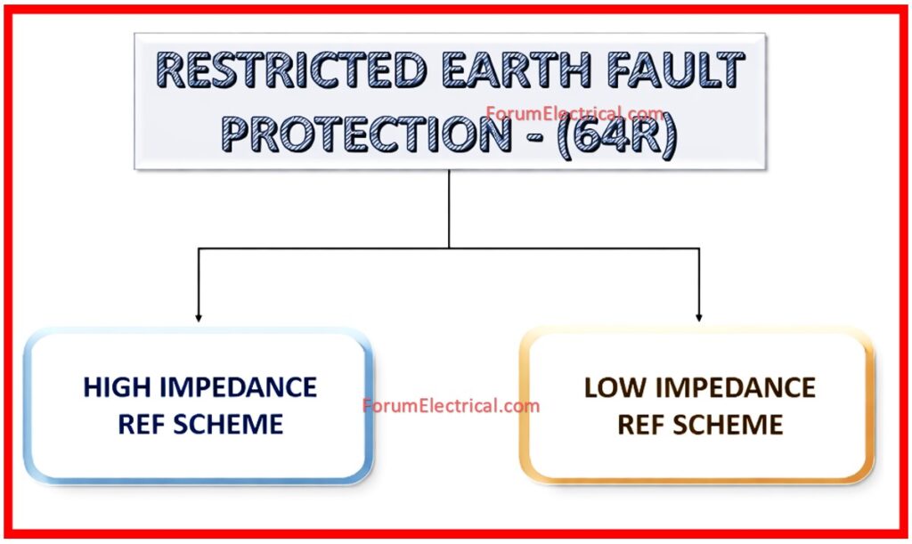
There are 2 types of REF Protection
- High Impedance REF
- Low Impedance REF
1). High Impedance REF
High impedance REF requires stabilizing resistor.
High impedance REF is a simple scheme.
It is widely used.
2). Low Impedance REF
Low impedance REF uses numerical relay.
Low impedance REF does not require stabilizing resistor.
It has better flexibility and stability.
Modern digital relays use only low impedance REF schemes.
Practical Considerations for REF Implementation
To ensure a reliable operation:
- CT ratios should match accurately.
- CT polarity should be correct.
- CT knee-point voltage should be adequate.
- Neutral CT should be properly positioned.
- Wiring resistance should be minimized.
Incorrect CT selection may cause:
- False tripping.
- Failure to operate.
Important Perspective
Restricted Earth Fault protection provides an essential, fast and highly sensitive detection layer for the internal earth faults in transformers which follows NEMA 250 standard.
Because it operates only within a restricted zone:
- It enhances reliability.
- It minimizes equipment damage.
- It improves protection selectivity.
- It strengthens HV substation safety.
REF protection is not optional in modern HV substations but it is a standard best practice for all transformer protection.
What is 50N and 51N Protection?
50/51 relays is used to protect the system from phase faults which includes
- Short circuits and
- Overloads.
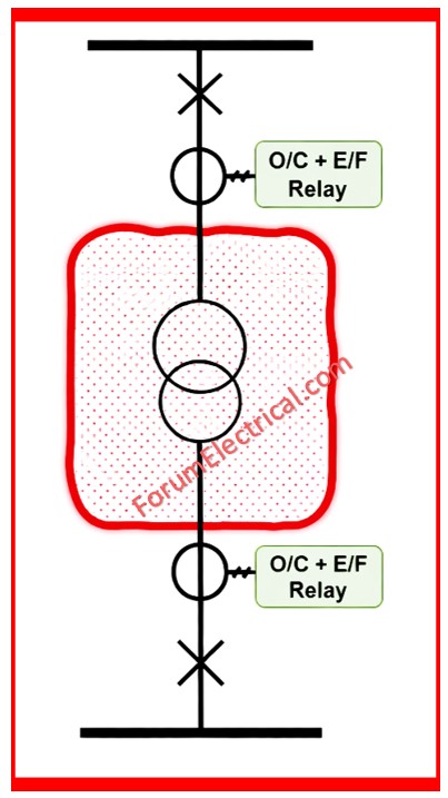
50N/51N relays enhances protection against the neutral faults.
50G detects ground faults that is important in systems with solid (or) low resistance grounding.

 for transformer protection including wiring diagram, operation and relay settings.)