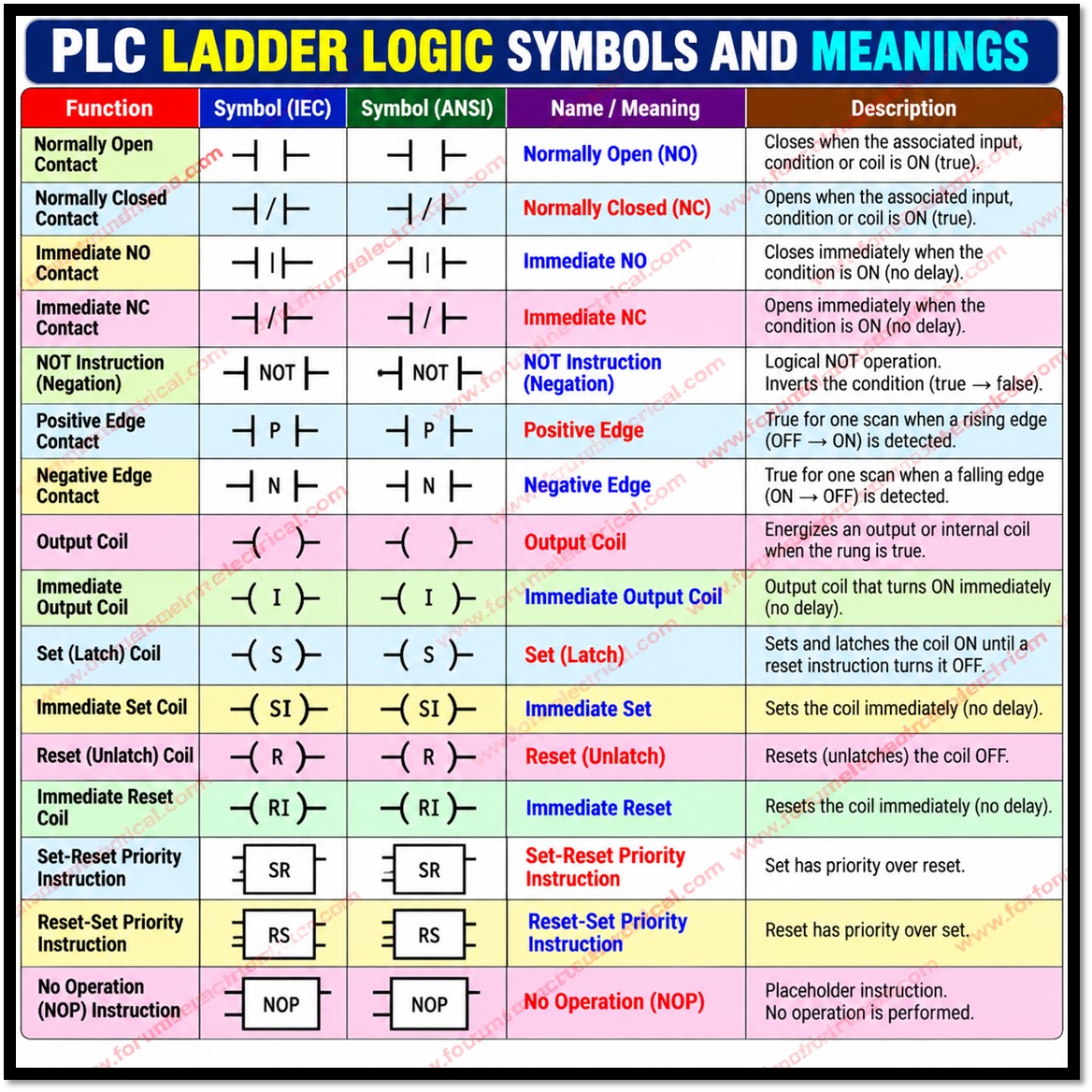
Ladder Diagram (LD) is a graphical PLC language standardized in IEC 61131-3 and modelled on electrical relay schematics.
A program is a set of rungs drawn between two vertical power rails.
Each rung combines input conditions (contacts) on the left with output actions (coils) on the right.
When the contacts form a continuous logical path, “power flow” reaches the coil and the output is acted upon.
Bit logic instructions operate on single Boolean bits (1 or 0) and are the foundation of machine control, interlocking and sequencing.
Scan Cycle
A PLC executes its program cyclically.
In each scan it copies physical inputs into an input process image that executes the program logic using that image and then copies the output process image to the physical outputs.
Standard instructions therefore work on a snapshot and a terminal that changes mid-scan is not seen until the next scan.
This delay is that the “immediate” instructions are designed to bypass.
Contacts (Conditions)
Contacts test the state of a bit and decide whether the power flow continues along the rung.
- Immediate NO/NC: These behave like NO/NC contacts but read the physical input terminal at the moment of execution rather than the process image. They apply only to physical inputs, not internal memory bits and are available on some platforms (for example, the Siemens S7-200 family).
- NOT (Negation): NOT inverts the power flow arriving at it: if flow arrives, it stops and if no flow arrives, it passes. It differs from an NC contact which inverts one bit whereas NOT inverts the combined logic result to its left.
- Positive Edge (P): It generates power flow for exactly one scan when the signal changes from OFF to ON. The PLC compares the current state with the previous scan’s state, so some platforms need a memory bit to store it.
- Negative Edge (N): It does the same for an ON to OFF transition. Edge contacts are utilized for one-time operations, counter increments & toggle circuits because maintaining a signal ON does not reactivate the instruction.
Coils (Outputs)
Coils sit at the right end of a rung and write the rung result to a bit.
- Output Coil ( ): The bit is ON while the rung is true and OFF when it is false. It is non-retentive and follows the rung every scan. Each coil address should appear only once in a program because with duplicate coils the last one executed overrides the others.
- Immediate Output Coil (I): It writes the result to the physical output immediately and also updates the process image without waiting for the end of the scan. It applies only to physical outputs.
- Set (Latch) (S): When the rung is true, the bit turns ON and stays ON even after the rung goes false. A false rung has no effect on it. Only a Reset instruction clears it. On some platforms a single Set can latch a range of consecutive bits.
- Immediate Set (SI): This works like Set but also writes the physical output immediately.
- Reset (Unlatch) (R): When the rung is true, the bit turns OFF. A false rung does nothing. Many platforms also use Reset to clear timers and counters.
- Immediate Reset (RI): It clears the physical output immediately as Set Immediate does for turning ON.
A classic latching circuit uses a Set rung driven by the Start button and a Reset rung driven by the Stop button.
Note that with separate Set and Reset coils, priority depends on rung order: the instruction executed last in the scan determines the final state.
Placing the Reset rung after the Set rung gives the stop command priority.
Special Instructions
- SR (Set-Reset): The following is a bi-stable (flip-flop) with 2 inputs: set and reset. If both are active at the same time, Set has priority and the output is ON. It is set-dominant.
- RS (Reset-Set): This is also a bistable but if both inputs are active, Reset has priority and the output is OFF. It is reset-dominant. Reset-dominant logic is generally preferred where a stop (or) safety command must always win such as motor control.
- NOP (No Operation): It performs no action and does not alter the rung logic. It serves as a placeholder to reserve program space (or) to temporarily replace an instruction during testing and debugging.
Summary Table
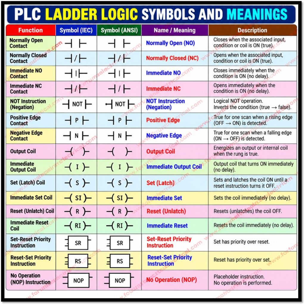
| Instruction | Symbol | Function | Note |
|---|---|---|---|
| NO contact | ─| |─ | Passes power flow when bit = 1 | AND in series, OR in parallel |
| NC contact | ─|/|─ | Passes power flow when bit = 0 | Typical for stop logic |
| Immediate contact | ─|I|─ | Reads physical input directly | Physical inputs only |
| NOT | ─|NOT|─ | Inverts incoming power flow | Acts on rung result |
| Positive edge (P) | ─|P|─ | One-scan pulse on 0 → 1 | Needs previous-state memory |
| Negative edge (N) | ─|N|─ | One-scan pulse on 1 → 0 | Needs previous-state memory |
| Output coil | ─( )─ | Follows rung state | Non-retentive |
| Immediate coil | ─(I)─ | Writes to physical output at once | Physical outputs only |
| Set / SI | ─(S)─ / ─(SI)─ | Latches bit ON | Holds until reset |
| Reset / RI | ─(R)─ / ─(RI)─ | Clears latched bit | Immediate variant for outputs |
| SR | Box | Set-dominant flip-flop | Set wins if both active |
| RS | Box | Reset-dominant flip-flop | Reset wins if both active |
| NOP | Box | No operation | Placeholder only |
Conclusion
Contacts evaluate conditions, coils execute actions, and special instructions resolve priority and structure.
Choosing between standard and immediate instructions, and between plain coils and latching instructions, directly affects timing, safety and reliability.
Because naming, symbols and availability of some instructions (especially immediate ones) differ between manufacturers, programmers should always confirm its function in the documentation of their specific PLC platform.

