
A Programmable Logic Controller (PLC) is an industrial computer designed to monitor, control and supervise machines and processes in real time.
A PLC based automation system, however, is more than the controller.
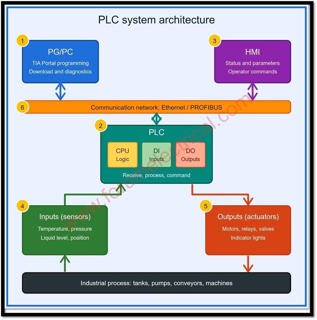
It is an integrated architecture of six elements:
- Programming device,
- PLC,
- Human-machine interface,
- Input devices,
- Output devices and
- Communication network.
This post analyzes each element, explains how they cooperate and highlights why the architecture is important for design, commissioning and troubleshooting.
System Overview
The architecture follows a closed-loop principle.
Field sensors report the state of the process to the PLC; the PLC evaluates those signals against its stored program and it then commands actuators to change the process.
Operators observe and influence the process through the HMI while engineers maintain the system via the programming device.
All of these devices exchange data over an industrial communication network.
| Component | Primary Function | Typical Examples |
|---|---|---|
| PG/PC | Programming, download, diagnostics. | Engineering laptop running TIA Portal. |
| PLC | Executes control logic. | CPU, power supply, I/O modules. |
| HMI | Operator display and command entry. | Touch panel, panel PC. |
| Inputs | Feed process data to the PLC. | Sensors, switches, transmitters. |
| Outputs | Carry out PLC commands. | Motors, valves, relays, lamps. |
| Network | Data exchange between devices. | PROFINET, PROFIBUS, Modbus TCP. |
PG/PC (Programming Device)
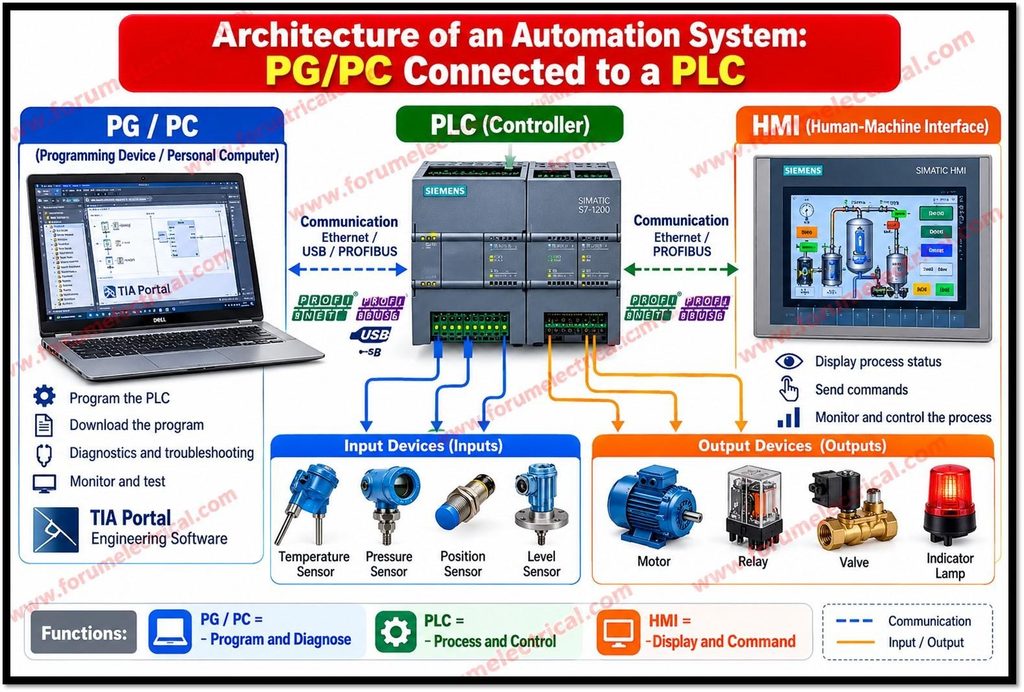
The programming device is typically a laptop (or) desktop computer loaded with engineering software.
In Siemens, this software is TIA Portal (Totally Integrated Automation Portal), which combines
- PLC programming,
- HMI configuration,
- Network setup and
- Device configuration
in a single environment.
Its main functions are:
- Development and editing: Engineers create and modify the control program using languages defined in IEC 61131-3 such as Ladder Diagram, Function Block Diagram, Structured Text and Sequential Function Chart.
- Downloading: The completed program and hardware configuration are transferred to the PLC usually over Ethernet.
- Diagnostics, testing, and troubleshooting: Online monitoring lets engineers watch live variable values, force (or) modify signals, review diagnostic buffers and locate hardware (or) logic faults.
PLC (Programmable Logic Controller)
The PLC is the central decision making unit.
A typical system includes
- CPU,
- Power supply and
- Digital and analog input/output modules
and may add communication processors (or) specialty modules.
It performs 3 core tasks:
- Receiving signals from field sensors,
- Processing that input data according to the programmed logic and
- Sending control commands to output devices.
The procedure that is commonly known as the scan cycle is used to carry out these activities in a cyclical sequence.
The CPU reads the state of the inputs into an image table that executes the user program from beginning to end and writes the resulting values to the outputs.
It also handles communication and internal housekeeping tasks before the next cycle begins.
Because this cycle repeats continuously usually within milliseconds, the PLC provides deterministic & repeatable control.
HMI (Human-Machine Interface)
The HMI is the operator-facing layer of the system.
It is commonly a touch panel (or) industrial display connected to the PLC through the network.
It performs three primary functions:
- Display: It shows machine status, process values, alarms and parameters.
- Command entry: It allows operators to start (or) stop equipment, change setpoints, select modes and acknowledge alarms.
- Monitoring and supervision: The operators are able to follow the function of the procedure since it shows trends and alarm history.
The HMI does not execute the control logic.
It reads from and writes to PLC data, so the PLC remains the authority over control.
For larger plants, HMI functions are often extended by SCADA systems that supervise many controllers from a central location.
Inputs
Inputs bring information about the physical process into the PLC.
Sensors measure process variables such as temperature, pressure, liquid level, and position and provide feedback to the PLC.
Input signals fall into 2 primary categories:
- Analog inputs: continuously varying signals from transmitters and sensors commonly 4-20 mA (or) 0-10 V which the PLC converts to digital values through an analog-to-digital converter.
The quality of these inputs directly affects control accuracy since the program can only act on the information it obtains.
Outputs
Outputs convert PLC functions into physical action.
Actuators and control devices including
- Motors,
- Relays,
- Valves and
- Indicator lights
that execute the commands issued by the PLC.
Like inputs, outputs may be digital such as switching a contactor (or) lamp on and off (or) analog such as sending a 4-20 mA signal to position a control valve (or) set a drive speed.
Output modules may use relay (or) transistor switching which is selected according to the load and switching frequency.
Communication Network
The communication network ties the architecture together.
Industrial communication protocols including Ethernet-based protocols and PROFIBUS that enable data exchange between PLCs, programming devices, HMIs and other compatible equipment.
- Ethernet-based protocols: Examples include PROFINET, EtherNet/IP and Modbus TCP. They provide high bandwidth and support PLC-to-PLC links, HMI connections and program downloads.
- PROFIBUS: A fieldbus standard widely used to connect controllers with distributed I/O, drives and field devices over a serial network.
How the Components Work?
Consider a tank-filling process.
A level transmitter (input) sends an analog signal to the PLC.
The program compares the value to the setpoint and provides whether the inlet valve should open (or) close.
The PLC then commands the valve (output) accordingly.
Meanwhile, the HMI displays the level, lets the operator change the setpoint and raises an alarm if the level is abnormal.
If the program requires modification, an engineer connects the PG/PC, edits the logic in TIA Portal and downloads the revision.
Every one of these exchanges depends on the network.
Engineering Significance
Understanding this architecture is essential for control system design, commissioning and troubleshooting since faults can be isolated by finding whether they depend on the field device, I/O module, program logic (or) network.
Conclusion
A PLC system is a coordinated set of 6 elements.
The PG/PC creates and maintains the program, the PLC executes it, the HMI gives operators visibility and control, inputs supply process information, outputs act on the process and the communication network connects everything.
Engineers who understand how these parts interact can design more reliable systems, commission them faster and diagnose faults more effectively.

