
- What is a Clamp Meter?
- Working Principle of Clamp Meter
- Construction of Clamp Meter
- 1). Jaws/Transformer Clamps
- 2). Clamp Opening Trigger
- 3). Power Switch
- 4). Backlight Button
- 5). Hold Button
- 6). Negative (or) Ground Input Terminal
- 7). Positive Input Terminal
- 8). LCD Display
- 9). Functional Rotary Switch
- How Clamp Meter works?
- How to measure Current using a Clamp Meter?
- Types of Clamp Meter
- 1). AC Clamp Meter
- 2). DC Clamp Meter
- 3). DC and AC Clamp Meter
- 4). Flexible Zaw Clamp Meter
- 5). Current Transformer Type Clamp Meter
- 6). Iron Vane Type Clamp Meter
- 7). Hall Effect Clamp Meter
- Clamp Meter Measurement Types
- Clamp Meter Specifications
- Advantages of Clamp Meter
- Disadvantage of Clamp Meter
- Applications for Clamp Meter
- Safety Precautions of using Clamp Meter
- Difference between Clamp Meter and Multimeter
- Clamp Meter V/S Multimeter
- How do you measure voltage on a clamp meter?
- Summary
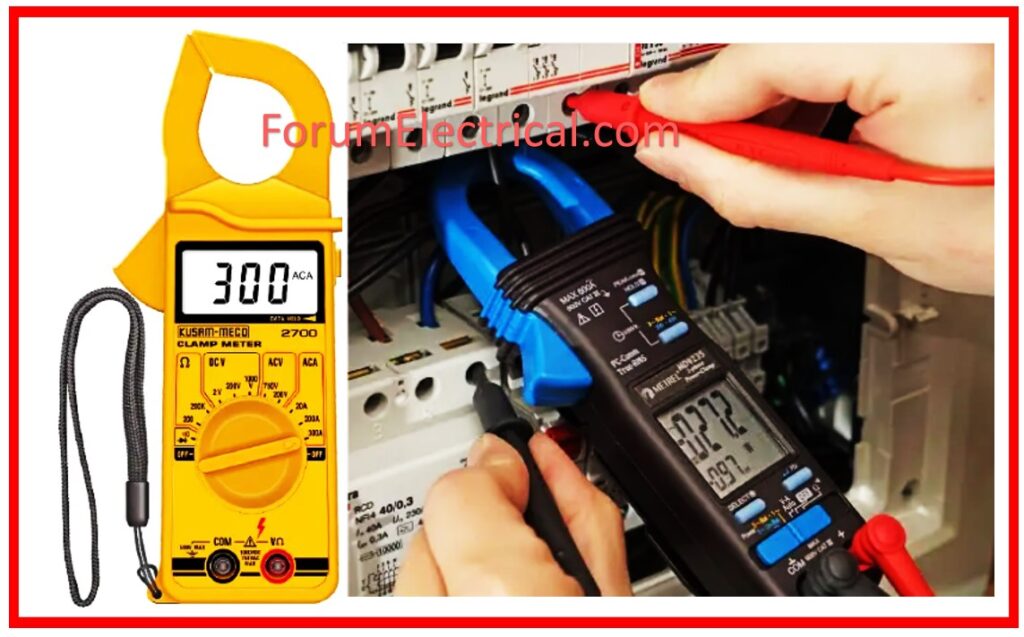
A clamp meter, commonly known as Tong Tester, are one type of test equipment. This technology is really simple to use & operate.
The primary function of this equipment is to detect a live conductor in a circuit without causing harm (or) power loss.
This device allows one to measure high-value current without turning off circuit during testing.
The primary disadvantage of this meter is that the long tester accuracy is substantially lower.
This post provides an overview of a clamp meter, its construction, and how it works.
What is a Clamp Meter?
Clamp meters are devices that measure current in an efficient, convenient, & safe manner without the use of test leads.
We know that magnetic fields can form when current runs through a conductor.
These instruments do not disturb the flow of current, allowing specialists to measure swiftly and safely.
Unlike multimeters, this design allows you to measure current without having to cut the circuit being measured.
Clamp meters are broadly classified into two types:
- Models intended to measure the load current
- Models intended to measure the leakage current
Instruments can also be classed based on other characteristics, such as whether they measure
- Direct Current (DC) (or)
- Alternating Current (AC), &
whether they employ mean value rectification or the RMS technique. Standard alternating current circuits are measured using load current models.
Some newer clamp meter models can detect both load and leakage current.
Working Principle of Clamp Meter
The clamp meter uses the magnetic induction technique to generate AC current measurements without touch.
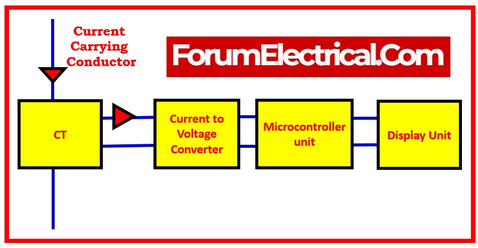
The flow of current across a wire creates a magnetic field.
The Hall Effect sensor monitors the magnetic field created by the flow of current, resulting in reduced voltage across the sensor.
It represents Faraday’s law, which states that a change in the magnetic field within a wire loop results in an electromotive force (EMF) in the wire.
- When the clamp is placed around a conductor, magnetic field is formed as current flows through it.
- The meter detects the change in magnetic field & transforms it to an electrical signal.
- The signal is subsequently analyzed and shown on the meter’s screen as the current reading.
Construction of Clamp Meter
This meter can be constructed using a wide range of components, which are explained below:
1). Jaws/Transformer Clamps
). Clamp Opening Trigger
3). Power Switch
6). Negative (or) Ground Input Terminal
7). Positive Input Terminal
8). LCD Display
9). Functional Rotary Switch
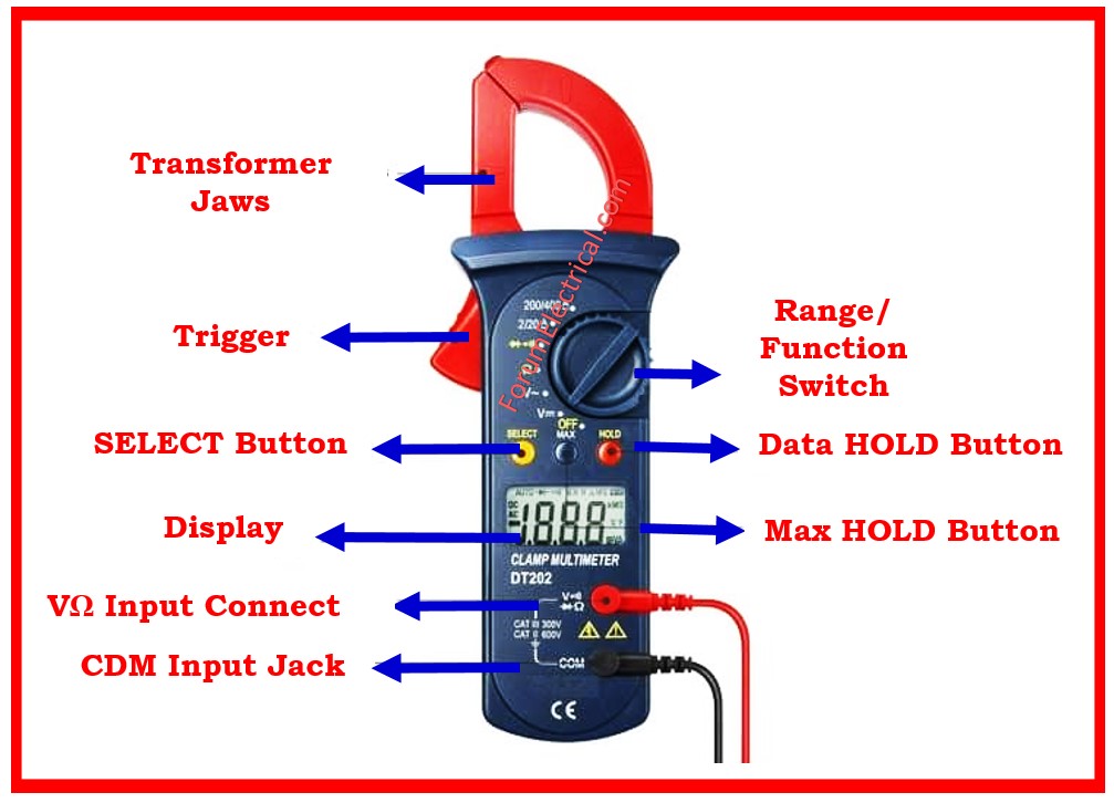
1). Jaws/Transformer Clamps
Transformer clamps (or) jaws are utilized to measure the magnetic field as the current flows through the wire.
2). Clamp Opening Trigger
Clamp opening triggers are used to open and close clamps.
3). Power Switch
The power switch is utilized to turn on/off the meter.
4). Backlight Button
5). Hold Button
6). Negative (or) Ground Input Terminal
The ground input terminal connects the ground jack (or) negative of the meter cable.
7). Positive Input Terminal
This terminal is utilized to connect the positive jack on the meter cable.
8). LCD Display
The measured value is shown on an LCD panel.
9). Functional Rotary Switch
This switch is utilized to select the current according to the range and type being measured.
How Clamp Meter works?
The steps described below can be utilized when operating a clamp meter.
Step-1: Connect the meter’s current probe.
Step-2: Connect the probe’s flexible tubing to the conductor.
Step-3: The probe & conductor must be at least one inch apart (2.5 cm).
Step-4: Rotate the dial to the desired symbol.
Step-5: Check the current value displayed on LCD panel.
How to measure Current using a Clamp Meter?
A clamp meter was employed to measure the current flowing across the instrument without touching it directly.
The non-contact feature allows for the measurement of the extremely high currents, that would otherwise be hazardous to the user and ensures a safe working environment.
A clamp meter can also be used to monitor continuity, measure voltage & resistance, & some models have temperature and frequency measurement functions.
Types of Clamp Meter
There are 7 different types of clamp meters:
- AC Clamp Meter
- DC Clamp Meter
- DC and AC Clamp Meter
- Flexible Zaw Clamp Meter
- Current Transformer Type Clamp Meter
- Iron Vane Type Clamp Meter
- Hall Effect Clamp Meter
1). AC Clamp Meter
AC clamp meters can only measure alternating current. They employ a transformer to detect magnetic field changes in the wire.
AC clamp meters operate using the current transformer law, which is used to detect magnetic flux generated as current flows across a conductor.
When the primary current runs over the conductor, the generated current is directly proportional to the current via electromagnetic induction from transformer’s secondary winding.
This allows you to measure AC values on LCD screen.
2). DC Clamp Meter
DC clamp meters measure direct current. They utilize a Hall Effect sensor to measure magnetic field changes surrounding the wire.
This equipment is used to obtain DC measurements.
Because the electromagnetic induction method for individual AC clamp meters is impractical, hall components are used as sensors to determine DC current.
A hall material is positioned in the gap created by severing a part of the transformer jaws.
When magnetic flux flows in proportion to the DC & AC currents in the jaws, the hall material detects it, and the flux reading is used to calculate the output voltage.
3). DC and AC Clamp Meter
A DC and AC clamp meter is a hand-held electrical testing equipment that measures current flow without making direct contact with the circuit.
It has a clamp-like jaw that monitors magnetic fields around a conductor, allowing for accurate & non-intrusive AC and DC current measurements.
AC clamp meters utilize current transformers (CT) & are widespread in domestic and industrial applications, whereas DC clamp meters utilise Hall effect sensors to measure stable DC currents and are frequently employed in battery, solar, & automotive applications.
Many modern clamp meters can also measure voltage, resistance, frequency, & continuity, making them valuable instruments for electricians and technicians.
4). Flexible Zaw Clamp Meter
This type of equipment is used with a Rogowski coil and entirely measures AC readings. It is mostly used for calculating narrow spaces.
The Rogowski coil current sensor looks and acts like a current clamp.
This coreless transformer is used by clamp meters as well as power monitoring loggers. It has superior linearity, no core to saturate it, can be made flexible, and does not require magnetic (or) electrical contact at the opening end.
Additional signal processing is required before the detected values can be shown, as the Rogowski coil generates a voltage proportionate to the rate of change of current in primary cable.
5). Current Transformer Type Clamp Meter
Current Transformer Type clamp meters can only measure alternating current (AC) values.
6). Iron Vane Type Clamp Meter
The moving iron vane is impacted by the core’s magnetic flux, allowing both DC & AC readings to be measured and providing RMS value for non-sine AC signals.
Due to its physical size, this iron vane clamp meter is often limited to power transmission frequencies of up to 100 Hz.
The device is often attached directly to the pointer’s display instrument, and the instrument’s calibration is completely nonlinear.
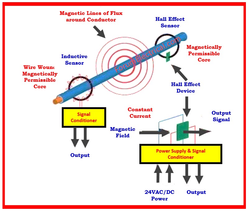
7). Hall Effect Clamp Meter
Clamp meters based on the hall effect may measure both alternating & direct current values.
The Hall effect type may measure both AC and DC, with some cases reaching kilohertz (thousands of hertz). It’s more sensitive.
This type was frequently employed in conjunction with oscilloscopes & costly computerized digital multimeters, but they are now being used for a wider range of applications.
Clamp Meter Measurement Types
AC Current Range
- 0A to 20A
- 0A to 200A
- 0A to 400A
- 0A to 1000A
Insulation Test Range
- 0A to 20MΩ
- 0A to 2000MΩ
AC Voltage Range
- upto 200V
- upto 750V
DC Voltage Range
- upto 20mV
- upto 2V
- upto 20V
- upto 200V
- upto 1000V
Resistance Value Range
- upto 200Ω
- upto 2KΩ
- upto 20KΩ
- upto 200KΩ
- upto 2MΩ
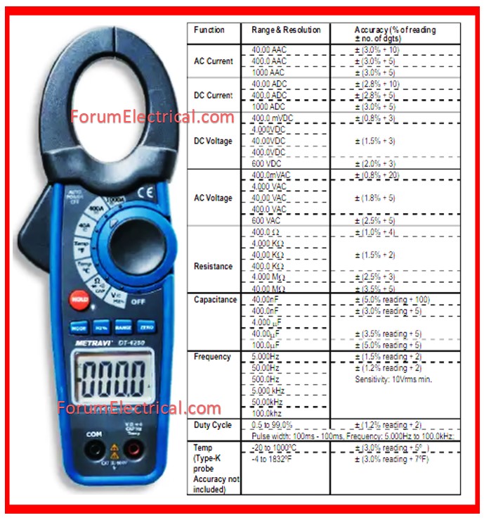
Clamp Meter Specifications
The clamp meter’s parameters vary greatly depending on manufacturing company.
Ex: The meter built by FLUKE mostly comprises the following:
- AC current ranges from 40.00 to 400.0 A.
- DC current ranges from 40.00 to 400.0 A.
- AC range voltage is 600.0 V.
- DC range voltage is 600.0V.
- The resistance range is 400.0 Ω, 4000 Ω, or 40.00 kΩ.
- The continuity is ≤ 30Ω.
- The capacitance range is 0-100.0 μF or 100-1000 μF.
- The frequency varies from 5.0 Hz to 500 Hz.
- The AC response is true-RMS.
- Backlight & Data Hold
- Contact temperatures vary from -10.0°C to -400.0°C.
- They provide a narrower current range, such as 0 A to 100 A.
- This range may vary depending on the model of meter, such as up to 600A.
- Some of the meter’s range is 999 A; else, 1400 A.
Advantages of Clamp Meter
- Safety: As there is no direct physical contact with circuit under test during the measurement method, a clamp meter ensures that very high AC currents are measured safely.
- Flexibility: Clamp meters enable ease of measuring current on active circuits, while frequently including common multimeter capabilities.
- Convenience: Because the circuit that carries current does not need to be turned off for measurements, circuit operation & testing can be done simultaneously.
- Identification of Faults: Easily identify faults during deployments.
- Cost Effectiveness: For continuous testing, maintenance, & service requirements
Disadvantage of Clamp Meter
- When comparison made to other measurement tools such as a multimeter, a clamp meter’s reading accuracy is poor.
Applications for Clamp Meter
- The primary function of these digital meters is to measure very high currents. These meters cannot gauge currents greater than 10A for more than 30 seconds (30 sec) without sustaining damage.
- These meters are commonly used in industrial, commercial, & residential HVAC systems.
- These are used to repair accessible systems.
- Engineers and technicians use clamp meters to test final circuits, diagnose electrical instrument maintenance concerns, and do other duties.
- It is also used to supervise a new electrician when they install electrical equipment.
- The clamp meter is employed to perform normal, emergency, and diagnostic maintenance.
Safety Precautions of using Clamp Meter
- When using a clamp meter, ensure the pointer is appropriately set to zero using the adjuster.
- The part’s range must be properly selected, as well as the knob that corresponds to that range.
- The range value should be selected higher, for example, the voltage range should be retained at 750 volts.
- For current measurement, connect the meter in series.
- In the presence of voltage in the circuit, resistance should not be measured.
- Keep your hand or finger away while measuring high voltage.
Difference between Clamp Meter and Multimeter
Clamp Meter V/S Multimeter
| Clamp Meter | Multimeter |
 |  |
| To determine the amount of current, a clamp meter is utilized. | A multimeter is utilized for the purpose of measuring resistance, voltage, and even less current. |
| The high current is measured by these meters. | These meters have a higher level of accuracy and provide a higher resolution. |
| Appropriate for determining the speed of the machine as well as the current drawn. | Suitable for use in electrical equipment. |
| One of the advantages of this meter is that it is more compact. | One of the main advantages of this meter is that it is lightweight. |
| More operations are accessible, and it is able to be protected from hazards. | Battery life is the primary disadvantage of this meter, which is an adverse effect. |
How do you measure voltage on a clamp meter?
When the clamp is tightly fastened around one conductor, the meter will show the current passing through it.
For voltage measurements, connect the probes to the appropriate test points: one to the live wire & the other to the neutral or ground line.
The voltage level will be displayed on the meter screen.
Summary
Thus, this is a general summary of clamp meters. In general, these meters are safer to use than multimeters.
Multimeters, on the other end, allow for accurate measurements because they must make contact with the circuit.
This post has provided a comprehensive overview of what a clamp meter is, including its working principle, construction, types, specifications, & applications.
Furthermore, it is important to have a thorough understanding of clamp meter household applications.


