
Transformers are alternating current (AC) devices that move electricity from one circuit to another.
- Basic Transformer
- Insulation in Transformer
- Purpose of the Insulation Resistance Test in a Transformer
- Procedure for an Insulation Resistance Test
- What is IR tester?
- Why DC instead of AC?
- Steps for troubleshooting poor IR values in a Transformer
- Step-1: Preliminary Checks
- Step-2: Initial Testing
- Step-3: Identify Potential Causes
- Step-4: Detailed Analysis
- Step-5: Corrective Actions
- Step-6: Re-Testing
Transformers enable to increase (or) decrease the voltage, often known as step-up or step-down, or to give electrical isolation.
One of the most important tests for any transformer is the insulation resistance test. In this post, we will demonstrate how to troubleshoot poor IR values.
Basic Transformer
One of the most frequently used applications for transformers is in power distribution networks.
The power that is delivered to the residence is stepped up and down several times before it arrives.
Any appliance that requires a voltage other than that provided by the common AC supply will almost certainly have a transformer installed.
The most basic transformer consists of two electrically separated windings wrapped tightly around an electromagnetic core.
When alternating current is applied to one winding, the other winding generates an AC voltage of the same frequency at a level determined by the winding’s turn ratio.
Insulation in Transformer
The windings are physically touching, and the coating on the windings is the only thing keeping the current from flowing from one to the other.
This coating on transformer wires is an example of electrical insulation. An ideal electrical insulator, by means of definition, prevents current flow. However, there is no such thing as an ideal insulator.
All insulators possess a breakdown voltage that implies that if the voltage across them is high enough, current can flow.
The current will vary extremely small, on the order of micro (or) nanoamps, but it will be greater than you would anticipate from an insulator; this is known as leakage current.
Purpose of the Insulation Resistance Test in a Transformer
The amount of leakage current depends on the winding insulation’s integrity.
Ex: Insulation may deteriorate over time owing to high temperatures or dampness, or exposure to voltages higher than the standards.
In this condition, the voltage level that the insulation had previously been able to withstand may have decreased, resulting in increased leakage current.
The performance of a transformer is determined by its construction, among other factors, and if the insulation is not consistent, it will function badly or even be dangerous in some conditions.
The insulation resistance of a transformer is primarily used to test the integrity of the winding insulation.
Better insulation will result in decreased leakage currents and improved performance and safety.
Procedure for an Insulation Resistance Test
Ohm’s law states that the current in a circuit is proportional to both the voltage across it & its resistance.
A resistance tester, such as an ohmmeter, employs this principle to determine a circuit’s resistance.
Ex: The battery of an ohmmeter gives voltage to a resistor, and the meter displays the resistance based on the amount of current flowing through it.
In an insulation resistance test, the basic idea is the same.
The key difference is that the resistance you’re attempting to measure now is incredibly high due to its insulating properties.
To measure increased resistance, you’ll need to apply a high voltage across it.
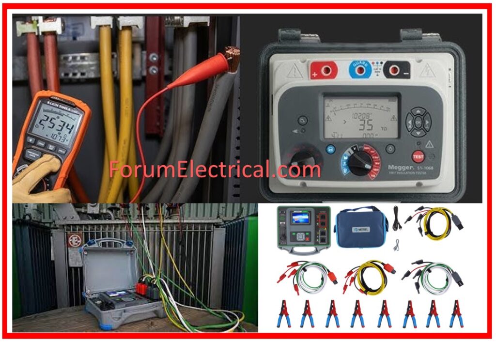
What is IR tester?
A standard ohmmeter cannot provide this, thus we must use a specialized ohmmeter that can provide greater voltages. Here comes the insulator resistance tester, commonly known as an IR tester. An IR tester will have various voltage settings; even the most basic models will feature 250V and 500V. The one we’re using here has 100, 250, 500, and 1000 volts. All of these voltages are direct current (DC).
Why DC instead of AC?
DC (or) direct current, delivers a constant flow of current to the insulator. It is equivalent to placing continual pressure on it in order to determine if it breaks down, which it will – eventually.
As a result, it is essential not to expose the insulation to high voltages for extended periods of time.
AS/NZS 3000:2018 – Australian and New Zealand electrical standard, popularly known as the Wiring Rules, states in Clause 8.3.6.2 Method that “the integrity of the insulation is emphasized by applying a direct current (DC) at 500V for low voltage circuits.” With some instances, the test voltage can be decreased to 250V.
Steps for troubleshooting poor IR values in a Transformer
It is necessary to use a systematic procedure in order to discover and resolve the underlying problems in order to troubleshoot poor (Insulation Resistance) IR values in a transformer.
Insulation resistance (IR) values are frequently a concern that we come across during the process of testing and commissioning transformers.
The following is a step-by-step guide that guides you through the process of troubleshooting poor (IR) Insulation Resistance values:
Step-1: Preliminary Checks
Safety Precautions: Before we begin testing, we must ensure that all safety standards are followed, particularly de-energizing and correctly grounding the transformer.
Visual Inspection: Look for visible indicators of corrosion, oil leaks, moisture infiltration, or contamination on transformer.
Step-2: Initial Testing
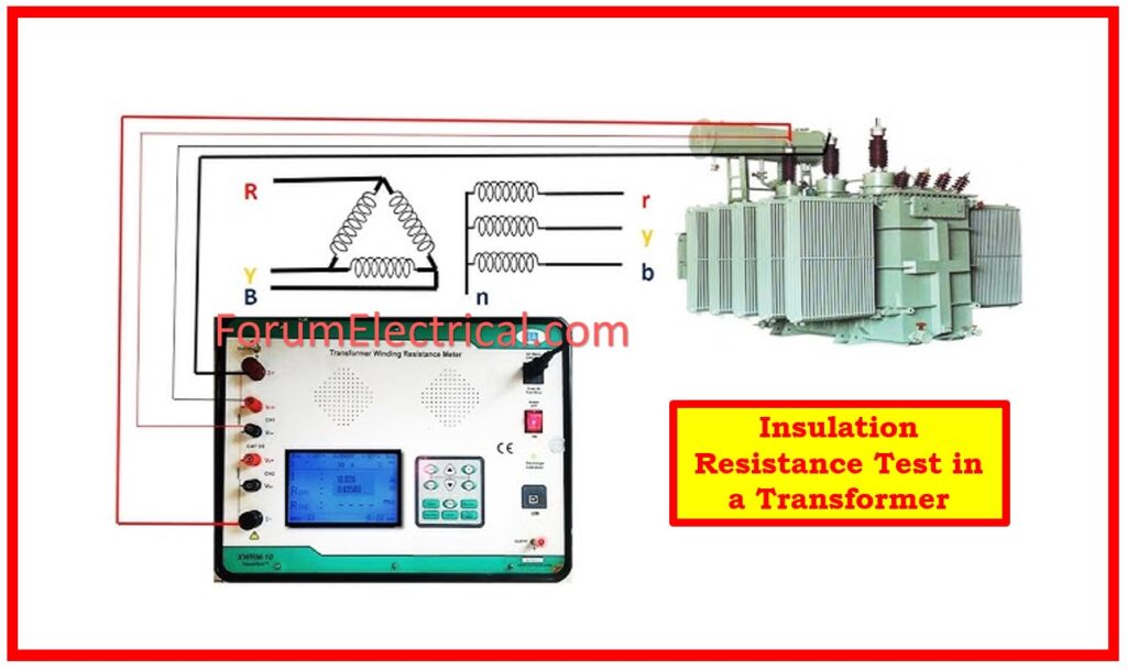
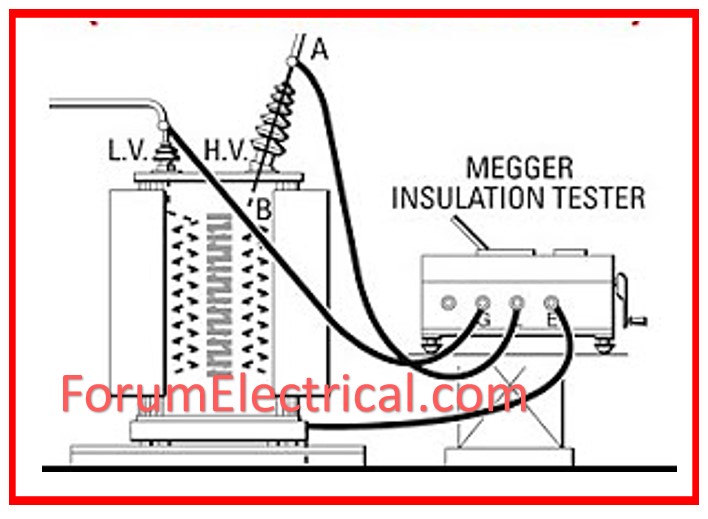
Measure IR Values: Measuring IR values between windings and between windings and ground should be done with a Megger (or) insulation resistance tester. Keep a record of these values.
Tan-delta testing of all bushings & windings is also required to ensure that the values fall within acceptable limits.
Compare to Standards: Compare the measured infrared values to the manufacturer’s specs or industry standard. A healthy transformer should have IR values in the hundreds of megaohms or greater.
Step-3: Identify Potential Causes
Moisture Ingress: One of the most prevalent causes of low IR values is moisture in the insulation paper (or) oil.
Contamination: Dirt, dust, and other pollutants can lower insulating resistance.
Internal Faults: Internal faults can also cause the IR value to be low.
Aging & Deterioration: Insulation materials may degrade over time, resulting in decreasing IR values.
Oil Quality: In oil-immersed transformers, poor oil quality might affect insulating resistance.
Temperature: IR readings might vary depending on the temperature. Ensure that measurements are taken at constant temperatures or adjusted to a standard temperature.
Step-4: Detailed Analysis
Internal defects, such as winding faults, or if any of the HV, IV, LV, or tertiary bushing leads come into contact with the transformer’s body, will result in almost zero IR.
A thorough internal inspection is required to detect these faults.
Bushing Failure: Bushing insulators failure might also result in low IR values.
Moisture Analysis: Conduct a moisture analysis of insulating oil (for oil-filled transformers) utilizing procedures such as Karl Fischer titration.
Oil Quality Test: Check the dielectric strength, acidity, & other properties of the transformer oil to ensure they are within acceptable limits.
Winding Resistance Test: Test for winding resistance to detect any shorted turns (or) inter-turn insulation problems.
Sweep Frequency Response Analysis (SFRA): Use SFRA to determine the mechanical integrity of the windings and core.
Step-5: Corrective Actions
Drying Out: If moisture is detected, dry the transformer utilizing methods such as vacuum drying, hot oil circulation, or an oil filter machine.
Cleaning: Remove any impurities from the transformer’s surfaces and insulation.
Oil Filtration: If the oil is of poor quality, filter it or replace it. Before refilling, make sure the oil is completely degassed and dry.
Internal Fault Correction: If bushing leads (or) windings are found to be broken, they must be rectified and insulated properly.
Repair (or) Replace Insulation: If the insulation is severely deteriorated, you should consider repairing or replacing it.
Temperature Control: Keep the transformer within the recommended temperature range to avoid future degradation.
Sometimes we receive good LV-E IR values yet poor HV-E values in a transformer; in this condition, the probability of oil contamination in the OLTC chamber is quite high, so we need to filter the oil in the OLTC chamber; it has been observed that after filtering the oil in the OLTC, HV-E IR values improve dramatically.
Filtration of the OLTC chamber separately is a difficult process; however, the equalizing valve can be opened & the oil filtered in the main body.
Step-6: Re-Testing
Re-Measurement: After adopting corrective actions, re-measure the IR values to confirm they are within acceptable limits.
Long-Term Monitoring: Set up a regular monitoring & maintenance program to evaluate IR values and other vital parameters.
By following these methods, we may systematically detect and repair faults that cause low IR values (Insulation Resistance value) in a transformer, assuring its long-term reliability and safety.


 values in transformers. Discover typical reasons, diagnostic procedures, and solutions for improving transformer performance and safety.)