
What is Tan Delta test?
Tan Delta testing, also known as Loss Angle (or) Dissipation Factor testing, is a diagnostic method that is used to test electrical equipment to verify the integrity of the insulation. Tan Delta testing can also be referred to as “Tan.” This is done in an effort to estimate the amount of time the equipment has left before it needs to be replaced.

Fundamentals of the Tan Delta Test
When connected across a line and the earth, a pure insulator acts like a capacitor. Since the substance that serves as both an insulator and a dielectric in an ideal insulator is completely pure, only a part of the electric current that passes through it is capacitive. Since there are no impurities at all in an ideal insulating material, there is no resistive component to the current traveling from the line to the earth through the insulator.
The capacitive electric current in a pure capacitor lags the applied voltage by 90 degrees.

The insulator can’t actually be rendered completely pure. Impurities like dirt & moisture infiltrate insulators as they age, which is another reason for this. The conductive channel for the current is provided by these impurities. As a result, a resistive component is present in an electric leakage current that travels through the insulator from the line to the ground.
Therefore, it goes without saying that the resistive portion of electric current leakage is relatively small for good insulators. Another technique to assess an electrical insulator’s health is to look at the ratio of its capacitive to resistive components. This ratio should be relatively small for an adequate insulator. The symbol for this ratio is tanδ or tan delta. It is also known as dissipation factor.
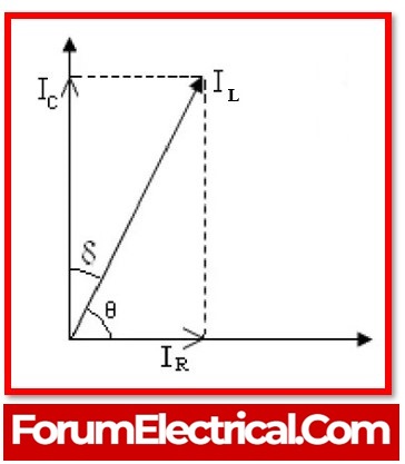
The system voltage is depicted along the x-axis in the vector figure above. Along the x-axis will also be conductive electric current, commonly known as the resistive component of the leakage current, or IR.
The leaking electric current IC‘s capacitive component will be drawn along the y-axis as it leads the system voltage by 90 degrees.
The total electric leakage current, IL(IC + IR), now forms an angle, with the y-axis.
Now that the preceding figure has been explained, it is obvious that the ratio of IR to IC is simply tanδ or tan delta.
Tan δ = IR/IC
Where,
IR= Resistive component of the leakage current
IC = Capacitive component of the leakage current
This particular δ angle is referred to as the loss angle.
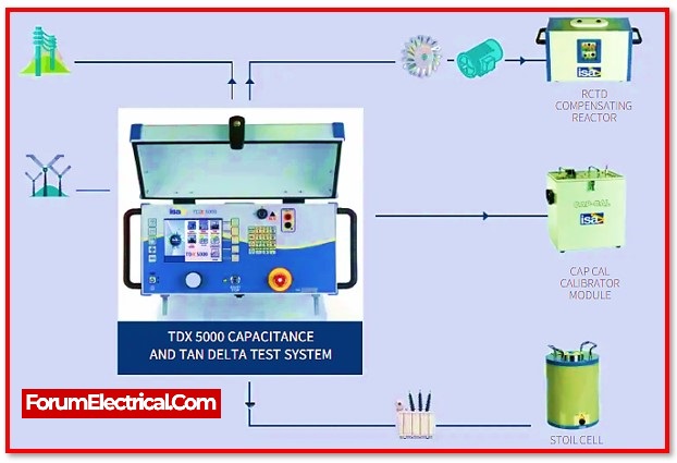
Tan Delta Testing Procedure
Initially, the system is disconnected from the
- Cable,
- Winding,
- Current transformer,
- Potential transformer, and
- Transformer bushing
that will be used for the tan delta test or dissipation factor test.
It is necessary to evaluate the insulation of the equipment by applying an extremely low-frequency test voltage across it.
The standard voltage is applied initially. If the tan delta value seems acceptable adequate, the applied voltage is increased to 1.5 to 2 times the equipment’s typical voltage. Tan delta values are measured by the tan delta controller unit.
Tan delta values at the normal voltage & higher voltages are compared with each other and the findings are analysed using a loss angle analyser attached to the tan delta measuring device.
It is essential to use test voltage at low frequencies during the test.
The reason for using Very Low Frequency
When the applied voltage frequency is high, the insulator’s capacitive reactance decreases, increasing the capacitive component of the electric current. The conductivity of the insulator and the applied voltage determine the amount of resistive component is basically fixed.
The vector sum of the capacitive & resistive components of the electric current has a significant amplitude at high frequencies because capacitive current is huge.
As a result, a practical tan delta test requires an apparent power requirement that is too large.
Very low-frequency test voltage is therefore necessary to maintain the power needed for this dissipation factor test.
Depending on the size and type of insulation, the frequency range for the tan delta test is typically between 0.1 and 0.01 Hz.
Another factor makes it essential to maintain the test’s input frequency as low as feasible.
In general,
Dissipation Factor = IR/ IC = (V/R)/(V X 2ΠfC) = 1/2ΠfCR
This indicates that the dissipation factor is tanδ ∝ 1/f.
As a result, when the frequency is low, the tan delta number is greater, and it is simpler to perform the measurement.
How to Predict Tan Delta Testing Results?
When performing a tan delta (or) dissipation factor test, there are two techniques to determine how an insulating system will function.
- The first method is comparing the outcomes of earlier testing in order to determine whether the insulation’s condition has deteriorated as a result of age.
- The second method involves directly estimating the state of insulation based on the value of tan δ. There are no responsibilities to compare prior tan delta test findings.
If the insulation is faultless, the loss factor will be roughly the same throughout the board for all test voltage ranges. However, the tan delta value rises in the greater range of test voltage if the insulation is insufficient.

It is seen in the graph that when test very low-frequency voltage grows, the tan and delta number increase nonlinearly.
An increase in tan & delta indicates a large component of resistive electric current in the insulation.
To make the appropriate option regarding whether the equipment needs to be changed or not, these outcomes can be compared to those of insulators that have already undergone testing.
Modes of Tan Delta Testing
The tan delta test, sometimes referred to as the power factor test, has a variety of operating modes to accommodate diverse testing conditions and requirements.
These modes allow for flexibility and a thorough assessment of the insulating system.
Let’s analyse the various tan delta test modes:
1). GST Guard Mode
In this mode, the tan delta test determines how much current leaks to the ground. The GST Guard mode stops current from leaking through the red (or) blue leads. The computation excludes the grounded edges.
Only the blue or red leads are used to measure current when the GST Guard mode is activated on the device.
Automatic bypassing of the ground lead current flow to the AC source means that it is not included in the computation.
By taking into consideration the leakage transmits to the ground, this mode helps in determining the insulating position.
2). UST Mode
The UST (Ungrounded Specimen Test) mode is used to determine how much insulation the equipment being tested ungrounded leads have between them.
In this mode, the insulation’s constituent components are removed and examined separately from any other insulation.
The UST mode enables a targeted evaluation of the effectiveness of the insulation by isolating particular areas of it.
It helps in recognizing and assessing the insulating qualities between unground components.
3). GST Mode
The final operation mode in tan delta testing is the GST (Grounded Specimen Test) mode.
The test device calculates both leakage paths in this mode.
- The wattage loss,
- Capacitance values,
- UST, and
- GST guards
must all match the GST test requirements.
The GST mode provides a thorough knowledge of the insulation performance by comparing these numbers.
Giving an in-depth inspection of the entire insulation performance, it takes into account both grounded & unground components.
It’s crucial to remember that if the GST Guard & UST values added together do not equal the GST parameters, there may be a problem with the test set or an error in the design of test terminals.
To obtain reliable and accurate tan delta test results in such conditions, additional research (or) troubleshooting may be necessary.
These various tan delta test modes provide individualized and comprehensive testing of the insulation system, facilitating efficient condition assessment & maintenance of electrical equipment.
Conclusion
The tan delta test, which can also be referred to as the power factor test, is an essential troubleshooting tool that is utilized for determining the state of the insulation of electrical apparatus.
This test helps identify potential problems and anticipate the performance & reliability of the insulation system by measuring the tan delta, the loss angle, and the dissipation factor.