
Purpose
The most basic and popular test for determining the strength of transformer insulation is the insulation resistance (IR) measurement. In addition to identifying any major internal defects in the transformer (such as the failure to remove the temporary transportation mounting on the live portion of the tap-changer part), this test also discloses the quality of the insulation, or the degree of dryness of the paper insulation.
Test Equipment
Meggers, available in 500 V, 1000 V, 2500 V, and 5000 V ratings, are used to assess insulation resistance. 2.5 kV megger is required for transformer windings with voltage ratings of 430V, 500V, 430V and above, 1000V megger, and 11 kV and above. It is preferred to use a 5 kV motorized or digital megger for measuring the IR values of EHV transformers.
Testing Procedures
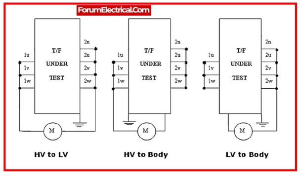
IR measurements must be obtained across the windings collectively (with all of the windings connected together) & the earthed tank (earth), as well as between each winding & the tank, with the remainder of the windings earthed.
Before collecting measurements, unplug the neutral from the earth.
The table below shows IR measurement combinations for
- Auto-Transformer,
- Three-Winding Transformer, and
- Shunt Reactor.
| Two Winding Transformer | Three Winding Transformer | Auto Transformer | Shunt Reactor |
| HV to Earth | HV+IV +LV to Earth | HV+IV to Earth | HV to Earth |
| HV to LV | HV+IV to LV | HV+IV to LV | – |
| LV to Earth | HV+LV to IV | LV to Earth | – |
Where,
HV- High voltage windings
IV-Intermediate voltage windings
LV-Low voltage windings
E- Earth
1). HV Windings to Earth
- Connect the Megger’s line terminal (5000V) to the Transformer’s HV winding.
- Connect the Megger’s Earth terminal to the earth pin provided at the electrical equipment.
- Turn ON the Megger.
- Record the readings (they need to be in MΩ).
2). LV Windings to Earth
- Connect the Megger’s line terminal (500V) to the Transformer’s LV winding.
- Connect the Megger’s Earth terminal to the earth pin provided at the electrical equipment.
- Turn ON the Megger.
- Make a note of the readings (they need to be in MΩ).
3). HV Windings to LV Windings
- Connect the Megger’s line terminal (5000V) to one of the Transformer’s windings.
- Connect the Megger’s Earth terminal to the Transformer’s other winding.
- Turn ON the Megger.
- Make a note of the readings (they need to be in MΩ).
Minimum Requirement
- Minimum 200 MΩ for below 6.6 KV class for 1 minute
- Minimum 400 MΩ between 6.6KV and 11KV classes for 1 minute
- Minimum 500 MΩ up to 33KV class for 1 minute
- Minimum 600 MΩ up to 132KV class for 1 minute
- Minimum 650 MΩ up to 220KV class for 1 minute
Core Insulation Check (2500V Megger)
| Core to Frame | Core to Tank | Frame to Tank | |
| Value Of Insulation For 60 Seconds |
Connection Diagram
Measurement Table
Temperature = 0C
| Measurement Between | 15 Seconds | 60 Seconds | 600 Seconds | DAI Value 60 sec/15 sec | PI Value 600 sec/60 sec |
| HV to Earth | |||||
| HV to LV | |||||
| LV to Earth |
Where,
DAI – Dielectric absorption coefficient (or) index
PI – Polarization Index
Precautions
1. Before testing, the temperature must be documented.
2. Testing cables should not have any joints.
3. Test leads must not come into contact with any live parts.
4. Earth the megger body (if a separate terminal is available).
5. Clean the surface/terminals.
6. IR Preferably, measurements should be taken in dry, sunny conditions.
7. Never connect energized equipment to the test set.
8. The ground terminal should be connected first & then disconnected.
9. After high voltage testing, test terminals should be grounded before any staff touch them.
10. Test leads must be adequately screened and shielded.