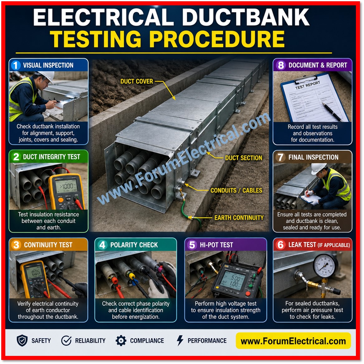
This procedure establishes the standard method for testing underground electrical ductbanks prior to, during, and after cable installation.
- Purpose and Scope
- Reference Standards
- Safety Requirements
- Pre-Test Inspection and Duct Integrity Verification
- Insulation Resistance (IR) Testing
- Continuity and Phase Identification
- High-Potential (Hipot) and VLF Testing
- Ground Continuity and Resistance Testing
- Acceptance Criteria
- Documentation and Reporting
- Retest and Non-Conformance Handling
Purpose and Scope
It applies to concrete-encased and direct-buried ductbank systems containing medium-voltage (MV) and low-voltage (LV) power conductors, and is intended for use by field engineers, testing technicians and quality control personnel responsible for verifying the physical and electrical integrity of the raceway and conductor system before energization.
The procedure covers duct integrity verification (mandrel and rodding tests), insulation resistance testing, continuity and phasing checks, high-potential (hipot) testing of medium-voltage cables, and ground continuity testing.
It does not cover transformer, switchgear, or relay commissioning, which are addressed under separate procedures.
Reference Standards
- NETA ATS – Acceptance Testing Specifications for Electrical Power Equipment and Systems
- IEEE Std 400 series – Guide for Field Testing and Evaluation of Shielded Power Cable Systems
- IEEE Std 43 – Recommended Practice for Testing Insulation Resistance of Rotating Machinery and Cable Systems
- IEEE Std 81 – Guide for Measuring Earth Resistivity, Ground Impedance, and Earth Surface Potentials
- NFPA 70E – Standard for Electrical Safety in the Workplace
- Project-specific drawings, cable schedules, and manufacturer test instructions
Safety Requirements
All testing shall be performed under an approved Job Hazard Analysis (JHA) and Energized Electrical Work Permit where applicable.
Personnel shall wear appropriate arc-rated Personal Protective Equipment (PPE) as determined by the incident energy analysis for the circuit under test.
High-potential and VLF testing introduces lethal voltages onto the cable under test; a documented lockout/tagout (LOTO) procedure, exclusion barriers, and dedicated grounding of the far end and adjacent circuits are mandatory before energizing any test set.
- Verify zero energy state with a rated voltage detector before connecting test leads.
- Establish a controlled test boundary with warning signage and, where required, a dedicated safety watch.
- Discharge and ground all cables immediately after high-voltage testing, allowing for capacitive discharge time appropriate to cable length.
- Confirm two-way communication between test set operator and personnel at the remote cable end before each test.
Pre-Test Inspection and Duct Integrity Verification
Before any electrical testing, each duct within the bank must be verified as clear, continuous and free of deformation.
This step protects cable during pulling and ensures the raceway meets design tolerances.
- Visually inspect manholes, handholes and duct terminations for damage, water intrusion, or debris.
- Perform a mandrel test by pulling a rigid mandrel, sized at least 90% of the nominal duct inner diameter, through each duct to confirm there are no crushed sections, offsets, or intrusions.
- Rod and swab each duct to remove debris, verify continuity end-to-end, and confirm the presence of a pull rope or fish tape.
- Record duct fill, spare capacity, and any deviations from the approved ductbank drawing in the pre-test inspection log.
Insulation Resistance (IR) Testing
After cables are installed and terminated (or prior to termination, per project sequencing), insulation resistance testing is performed using a calibrated megohmmeter to confirm the integrity of conductor insulation relative to ground and between phases.
- Apply test voltage in accordance with cable rated voltage: typically 500 VDC for LV control cable, 1000–2500 VDC for LV power cable, and 2500–5000 VDC for MV cable insulation.
- Record readings at 30 seconds, 1 minute, and 10 minutes to calculate the Polarization Index (PI), which indicates insulation condition trends over time.
- Test each phase conductor to ground and phase-to-phase, with unused conductors grounded during each measurement.
- Correct all readings to a 20°C reference temperature using standard temperature correction factors, since conductor temperature significantly affects resistance readings.
Continuity and Phase Identification
Continuity testing confirms that each conductor forms an unbroken path from origin to destination and that phase, neutral, and ground conductors are correctly identified and landed at both ends.
This is typically performed using a low-voltage ohmmeter or continuity tester in conjunction with a phasing voltmeter for circuits that will be paralleled or synchronized with an existing system.
Technicians at each end of the ductbank run coordinate to ring out every conductor individually, tag conductors according to the approved cable schedule, and document any deviation from the design phase rotation before the circuit proceeds to high-voltage testing.
High-Potential (Hipot) and VLF Testing
For medium-voltage cables, a very low frequency (VLF) withstand or tan delta test is generally preferred over DC hipot testing because it more accurately represents in-service AC stress without the risk of residual space charge that DC testing can leave in extruded dielectric cables.
The test is performed at a specified multiple of rated voltage for a defined duration per IEEE 400.2.
- Confirm cable is isolated from source and load equipment and properly grounded before connecting the VLF test set.
- Ramp voltage gradually to the specified test level and hold for the required withstand period, typically 15–60 minutes depending on cable voltage class and test standard selected.
- Monitor leakage current throughout the test; a stable or decreasing trend is acceptable, while a rising trend may indicate insulation degradation.
- Where diagnostic testing is specified, perform tan delta measurements to trend insulation aging independent of a pass/fail withstand result.
Ground Continuity and Resistance Testing
The ductbank ground conductor, along with any concrete-encased electrodes or ground grid tie-ins, must be verified for continuity and measured for resistance to confirm an effective fault-current return path.
A digital low-resistance ohmmeter (DLRO) is used for continuity and bonding checks, while a four-point fall-of-potential or clamp-on ground resistance tester is used for the overall grounding system where accessible.
Acceptance Criteria
The following table summarizes the primary test types and their associated acceptance criteria where project specifications or manufacturer instructions impose stricter limits, the more conservative value governs.
| Test | Standard/Reference | Acceptance Criterion |
| Insulation Resistance (IR) | IEEE 43 / NETA ATS | Minimum 100 MΩ (or per cable manufacturer); no continuous decreasing trend over test duration |
| Polarization Index (PI) | IEEE 43 | PI ≥ 2.0 for Class B or higher insulation systems |
| Continuity / Phase ID | NETA ATS 7.3 | Continuous conductor path, correct phase-to-phase correlation, no cross-connections |
| High-Potential (VLF/Hipot) | IEEE 400.2 / NETA ATS | No breakdown, flashover, or excessive leakage current during withstand period |
| Ground Continuity / Resistance | IEEE 81 / NETA ATS | Continuous ground path; resistance within design specification (typically < 5 Ω for the ductbank ground grid tie-in) |
Documentation and Reporting
All test results shall be recorded on standardized field data sheets or an electronic test management system, including test equipment used, calibration dates, ambient conditions, raw and temperature-corrected readings, and the name of the responsible technician.
Any failed test shall trigger a nonconformance report, root-cause investigation, and retest following corrective action. Completed test packages are submitted to the engineer of record for review and inclusion in the project closeout documentation prior to system energization.
Retest and Non-Conformance Handling
If a cable segment fails insulation resistance, hipot, or continuity testing, the segment shall be isolated, tagged, and reported immediately.
Root causes may include installation damage, moisture intrusion, defective terminations, or manufacturing defects.
Once corrective action such as re-termination, cable replacement, or duct repair is completed, the full test sequence relevant to the affected circuit shall be repeated in its entirety, not merely the specific test that failed, to confirm overall system integrity before final acceptance.

