
- Components of electrical substations
- 1). Electrical Transformer
- 2). Instrument Transformer
- 3). Conductors
- 4). Insulators
- 5). Isolators (Separators)
- 6). Lightning Arrester
- 7). Circuit Breaker
- 8). Wave-Trapper
- 9). Bus Bar
- 10). Batteries
- 11). Switchyard
- 12). Relay
- 13). Capacitor Bank
- 14). Carrier Current Equipment
- 15). Outgoing Feeders
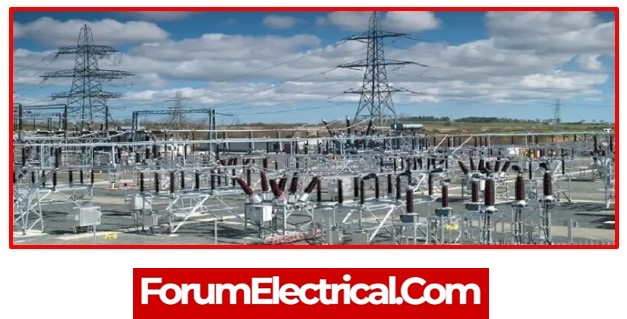
The power grid is an important element of the systems for generating, transmitting, and distributing electricity. For all functions of the power system, electrical substations are necessary.
These are essential instruments used in the substations to generate electricity. The quantity of power needed at substations to deliver energy to consumers may be altered by adjusting the levels of frequency and voltage.
Different types of electrical substations are listed below, including
- Generating,
- Pole-mounted,
- Indoor,
- Outdoor,
- Converter,
- Distribution,
- Transmission, and
- Switching substations.
The collector substation, which may be used for power transfer from the several turbines in a single transmission unit, can be seen in various conditions, such as thermal plants, multiple hydropower, and wind farms.
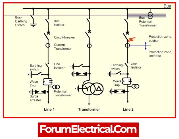
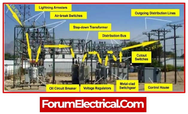
Components of electrical substations
Various electrical substation components, such as
- Isolators,
- Bus bars,
- Power transformers, etc.,
are coupled together at the substation and may be used to carry electrical power from the generation units to distribution. For the substation to be installed, the electrical substation equipment is necessary. The following are the key components of substation equipment & their purposes.
The design of an electrical substation is a difficult process that requires extensive engineer planning. Switching systems, equipment positioning and planning, component selection and ordering, engineer assistance, structural design, electrical layout design, relay protection, and primary apparatus ratings are some of the essential stages in substation design.
1). Electrical Transformer
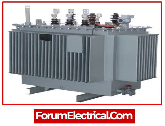
Electrical transformers are static electrical machines that transfer electricity from one circuit to another without altering frequency. Transformers are often employed to reduce or increase the voltage levels of the system for transmission & generating. These transformers are grouped into many varieties depending on their design, application, and installation techniques, among other factors.
Electrical transformers are used to increase transmission voltage at generating unit and decrease it at the distributing unit. Most of the time, oil-immersed, naturally cooled, & three-phase transformers are used for ratings up to 10MVA. Air blast cooled transformers are also employed when the required current is more than 10MVA.
A transformer of this type only provided power while fully loaded and was disconnected when the load was reduced. As a result, full-load conditions might maximise the electrical transformer’s efficiency.
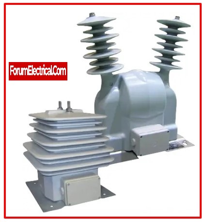
2). Instrument Transformer
An instrument transformer’s primary function is to reduce high current and voltage levels to a safe and practical level. With the use standard tools, these values may be determined. 110 V and 1A (or) 5A are the permissible ranges for voltage and current. By supplying both the current and the voltage, this transformer is also utilised to activate the protective relay.
These transformers may be divided into
- Voltage transformers and
- Current transformers,
respectively.
a). Voltage Transformer (Potential Transformer)
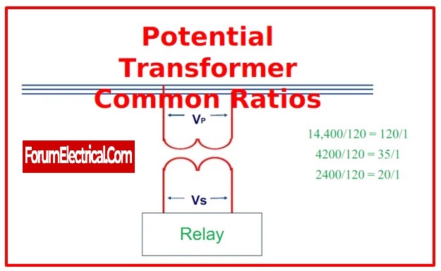
This transformer might be classified as an instrument transformer, which is a type of transformer that is used to reduce the voltage of an input signal from a higher value to a lower one.
While a potential transformer and a current transformer are relatively similar, the voltage transformer is used to sample high voltages from a system and provide low voltage to protection system relays as well as low-rating meters for voltage measurement.
The high voltage of the real system may be derived from the low-voltage measurement without directly measuring high voltages, saving on the expense of the measurement device.
b). Current Transformer
The primary purpose of a current transformer, an electrical device, is to change the current value from a higher value to a minor value. This kind of transformer may be used with meters, control equipment, and AC instruments in simultaneously.
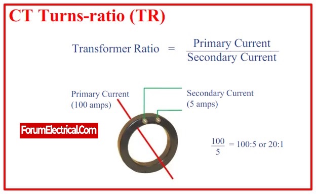
Alternating current is measured using a current transformer by obtaining samples of the system’s higher currents. These condensed samples accurately reflect the system’s actual high currents.
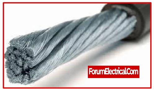
3). Conductors
The term “conductor” refers to any material or element that complies with the electrical property of conductance and permits the flow of an electric charge. The flow of an electrons via conductors is unrestricted.
These are used to transmit electricity or electrical energy through substations from one location (the generating station) to the another one (a consumer location where power is consumed by loads). Different kinds of conductors are used in actual power systems, although aluminium conductors are most often used.
4). Insulators
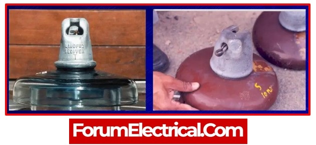
An insulator is a metal that restricts the free flow of an electrons (or) electric charge. As a result, insulators have a high resistance to electricity. Insulators come in a variety of forms, including
- Suspension insulators,
- Strain insulators,
- Stray insulators,
- Shackle insulators,
- Pin insulators, and more.
Insulators are used to prevent short circuits and meet other insulating criteria while building electric poles with wires.
5). Isolators (Separators)
An isolator is a manually controlled mechanical switch that separates a healthy segment from a damaged segment of a wire, circuit, or substation in order to prevent the emergence of more serious problems. It is also known as a disconnected (or) disconnecting switch as a result. Different isolator types, such as single-break isolators, double-break isolators, bus isolators, line isolators, etc. are utilised for various purposes.
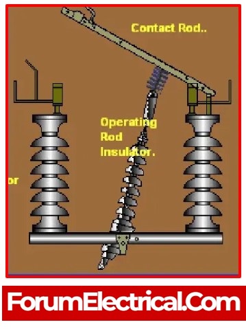
When the current flow has been interrupted, isolator is utilised to isolate the circuit. Isolators do not have any special current-making or current-breaking capabilities and are not incorporated into arc-quenching equipment. It can also be utilised to stop the transmission line’s current charging.
6). Lightning Arrester
Transformers, conductors, and other substation equipment are always constructed outside. Therefore, if there is a surge in light, a high voltage passes through these electrical components, damaging them (either permanently or temporarily, depending on the magnitude of voltage surge).
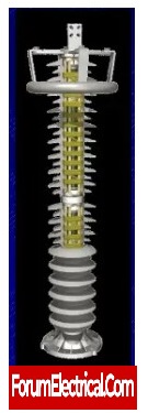
The primary purpose of this initial component in an electrical substation is to shield the other components from passing high voltage and to reduce the amplitude and duration of the current flow. The parts of the light arrestor are linked to the ground as well as a wire that runs parallel to the electrical substation’s defended parts.
7). Circuit Breaker
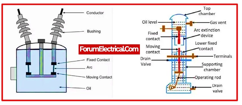
The problematic segment is detached from healthy section either manually (or) automatically in order to protect the substation and its components from over-currents or overload caused by short circuits or any other malfunction. Once the problem has been fixed, the original circuit may be manually or automatically reconstructed. Circuit breakers are constructed using a wide range of criteria and applications.
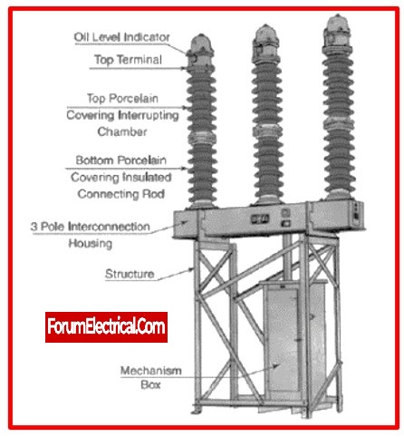
However, the most often used circuit breakers in general are
- Vacuum circuit breakers (VCB),
- Air circuit breakers (ACB),
- SF6 circuit breakers, and so on.
This type of an electrical switch is used to open or stop the circuit when a system mistake occurs. Two of its movable elements are typically closed. When a system mistake occurs, the relay sends a signal to the circuit-breaker, which causes each of its components to be moved independently. Therefore, when faults develop in the system, they become noticeable.
8). Wave-Trapper
On incoming lines, a wave-trapper is placed to capture the high-frequency signal. The current & voltage signals are interrupted by this signal (wave), which originates from the distant station. The high-frequency signal is tripped by this component and is sent to the telecom board.
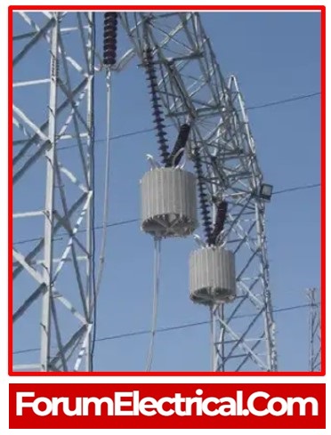
Therefore, lightning arresters are installed to pass the full lightning surge to earth in order to prevent this problem. Surge arresters are an additional type of arrester that is used to ground switching surges.
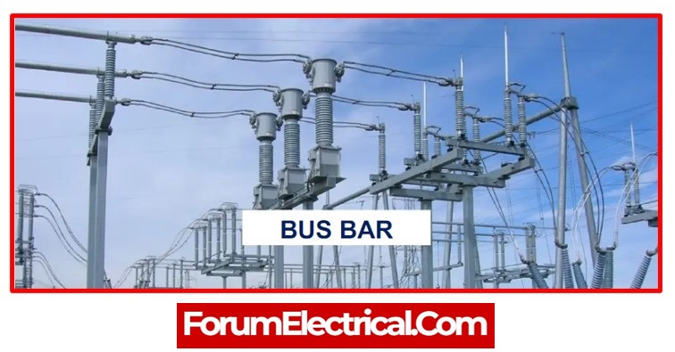
9). Bus Bar
A key component of an electrical substation is the bus bar. It is a type of conductor that may transmit current and has several connections. In simple terms, it may be explained as a certain kind of electrical connection that allows both incoming and outgoing current to flow.
As soon as this component develops a defect, all the circuit parts connected to that section need to trip out to provide complete isolation quickly so that the fitting doesn’t develop a failure due to conductor heating.
10). Batteries
Batteries are used to power the functioning of lights, relay systems, and control circuits in big power plants or substations. Depending on the DC circuit’s working voltage, these batteries are coupled to a certain accumulator cell.
- Acid-alkaline batteries and
- Lead acid batteries
are the two categories into which batteries categorised.
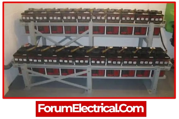
Because of their high voltage and very cost-effective low voltage, lead acid batteries are suitable for substations and power plants.
11). Switchyard
The switchyard serves as a link between the transmission and generation, and it maintains a constant voltage. The chosen level of voltage from the substation is sent to the nearby transmission line (or) power station via switchyards.
12). Relay
The major function of the relay, an electrical equipment at the substation, is to protect the grid component from abnormal circumstances like failures. This sort of detecting equipment is used to locate the fault and detect it, after which it sends a signal to circuit breaker.
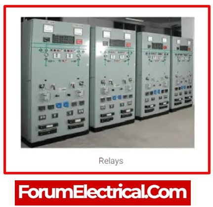
The circuit breaker will disconnect the defective component after it has received the signal from relay. Relays are mostly used for shielding equipment from dangers and harm.
13). Capacitor Bank
Capacitors incorporated inside this device are linked either in series (or) parallel. This device’s primary purpose is to store electrical energy in the form of electrical charges.
This bank pulls main current, which raises the system’s PF (power factor). The capacitor bank serves as a source of reactive power, which reduces the phase difference between the current and the voltage.
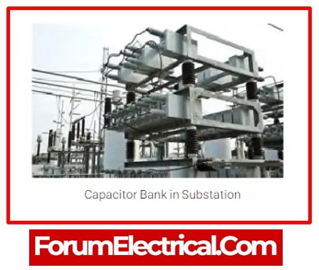
They will increase the power supply’s ability to handle ripple current, and they will get rid of any extraneous system features. The capacitor bank is an effective way to maintain power factor and address power-lag issues.
14). Carrier Current Equipment
For
- Telemetry,
- Supervisory control,
- Relaying, and
- Communication,
the carrier current equipment is permanently installed in the substations. By connecting to high-voltage power circuit, this equipment is properly installed in a control room station.
15). Outgoing Feeders
There are several outgoing feeders, and all of them are linked to the substations in a certain manner. The connection is made with the busbar system of the substation, which is responsible for transferring electricity from the substation to the service points.
The feeders may run above, below, or even above the streets, and they are responsible for transporting electrical power to distribution transformers located at either nearby or far away establishments.
Both the isolator in the substation and the breaker of feeder are regarded to be components of the substation, and they are normally made of metal-clad. When there is a problem with the feeder, the protection will immediately notify the operator, who will then activate the circuit breaker.
There is more than one effort made to re-energize the feeder when a problem has been detected, whether that fault was detected manually or automatically.


