
What is a BLDC Motor?
Brushless DC (BLDC) motors are progressively replacing DC & AC motors due to their
- High efficiency,
- Silent operation,
- Compact size,
- Reliability,
- High operating speed,
- Low maintenance, and
- Outstanding speed-torque characteristics.
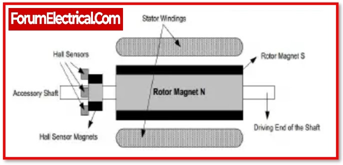
Motors with permanent magnets and brushless direct current (BLDC) are becoming increasingly popular due to the great power density they provide and the ease with which they can be controlled.
Brushless DC motors in the fractional horsepower (HP) range are being utilised in many various types of actuators in modern aircraft and satellite systems.
The most common brushless DC motors are three-phase and are regulated and powered by full bridge transistor circuits. In addition to using permanent magnet excitation, extra torque components must be obtained. These components can be acquired due to a variation in magnetic permeance in both quadrature and direct axis; as a result, reluctance torque is developed & torque null regions decrease significantly.
Outline
The BLDC motor speed is controlled and measured by this project utilising an IR speed sensor mechanism. In industries which employ drilling, spinning, lathes, elevators, etc., it is necessary to control the speed of a DC motor; as a result, this system provides an effective mechanism for accelerating or decelerating the speed.
There are three phases of the project.
- The first phase is the input phase, during which switches are used to enter the desired speed.
- The second phase of processing permits a motor’s RPM reference by integrating an 8051microcontroller with an IR sensor positioned on the shaft.
- To manage the DC power supply to the motor, the microcontroller creates PWM pulses in response to the input or switches. Additionally, an opto-isolator & a MOSFET are used in the output phase to drive a BLDC motor.
The microcontroller displays the speed on the LCD after receiving the speed measurement from the IR sensor.
BLDC Motor Speed Control Block Diagram with RPM Display System
Here is a block schematic of a BLDC motor speed control with the RPM display system that includes all necessary components.

Hardware Components
A list of the components used in BLDC motor speed control, along with an RPM display system is shown below
1). Transformer
2). Bridge Rectifier
3). Blocking Diodes
4). Voltage Regulator
5). LCD Display
6). UP and Down Switches
7). PIC Microcontroller
8). Circuit for Motor Drive
9). Speed Sensor
10). Fan Motor (BLDC)
1). Transformer
Transformers are used to connect directly to a power supply of 220V AC. On the basis of mutual induction, it converts 220V AC to 12V AC.
2). Bridge Rectifier
A bridge rectifier is utilised to convert alternating current voltages into direct current voltages for powering the entire system’s components. It is made out of an aggregate of four diodes.
3). Blocking Diodes
In this arrangement, the blocking diode is simply needed to prevent reverse polarity current, hence protecting the transformer. It includes a connection with the output of the bridge rectifier.
4). Voltage Regulator
The voltage regulator is utilised to regulate the 12V DC into 5V DC for feeding the voltages to the microcontroller and motor drive circuit. It is connected to the voltage regulator’s output. For this purpose, an LM 7805 voltage regulator IC is used.
5). LCD Display
The LCD display is utilised to display the RPM (revolution per minute) of the BLDC motor. It is a 16-pin LCD display with a 5V DC power source. It is linked to a microcontroller.
6). UP and Down Switches
This system with RPM display is comprised of two switches, Up and Down. Up is used to increase the speed of the BLDC motor, while down is used to decrease the speed. Both are linked to a microcontroller.
7). PIC Microcontroller
The PIC microcontroller 18F452 is utilised for intelligent control of this BLDC motor speed control with RPM display system. It is a 40-pin integrated circuit IC programmed in C using the micro software. It is powered by 5V DC and has an LCD display, up and down controls, speed sensors, and a motor driving circuit.
8). Circuit for Motor Drive
The motor drive circuit is utilised to operate the BLDC motor in the BLDC motor speed control with the RPM display system. It is made up of a power MOSFET and an optocoupler. The MOSFET is used to drive the motor at a different speed, while the optocoupler is used to bias the MOSFET at varying duty ratios.
9). Speed Sensor
Two IR sensors are utilised to measure the speed of the motor. One is the transmitter, which sends the infrared light, and the other is the receiver, which receives the infrared light when it collides with the shaft of the BLDC motor.
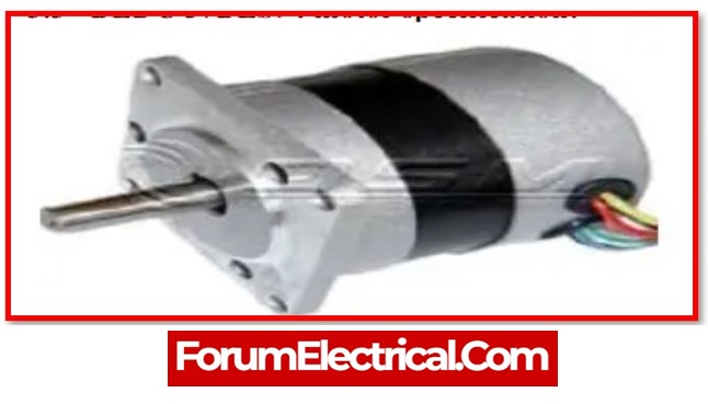
10). Fan Motor (BLDC)
The BLDC motor is utilised for speed control. This is a brushless DC motor supplied by a power inverter (or) switching DC source. It would be powered here by a switching dc supply.
Software Components
1). Keil µVision IDE
2). MC Programming Language: Embedded C
1). Keil µVision IDE
The complicated issues facing developers of embedded software are addressed by Keil 8051 development tools. Select the microcontroller that we will be using from the device database when starting a new project. All options for the Compiler, Assembler, Linker, and Memory are automatically specified by the Vision IDE.
2). MC Programming Language: Embedded C
The programming language that is most commonly used for electronic devices is embedded C. Every electronic system’s processor is linked to embedded software. Embedded C programming has a significant impact on the degree to which the CPU is able to complete specific operations.
Working principle of the BLDC Motor Speed Control with RPM Display
The BLDC motor speed control and RPM display system is based on the switching-DC-supply operating principle.
Changing duty ratio of the supplying voltages allows for the generation of the switching DC supply. The motor driving circuit in this system is activated at various duty ratios, & when it is triggered at various duty ratios, the motor runs at a variety of speeds.
The speed of a fan is managed by a microcontroller.
After the up switch is occurred, the microcontroller will adjust the duty ratio to a value between 10% and 80%. The duty ratio voltages will then be sent to the motor driving circuit, which will set the speed of the motor to a value between 0% and 100%.
In the same way, holding down the down switch and repeatedly pressing it can slow the speed of the engine until the required speed is reached.
IR sensors have been implemented into this system and interfaced with a microcontroller so that the RPM of the motor can be displayed on an LCD display.
After receiving the speed signal from the infrared sensors, the microcontroller counts each of revolution of the motor and then shows this speed at the LCD display in the form of a percentage, such as 10, 20, 80, or 100 percent.
As a result, we are able to run the BLDC motor at the necessary speed.
Advantages
- When compared to the other motor drive systems, this one is more space-efficient, has a higher efficiency, and has lower operating costs.
- When compared to previous systems, this one allows for more accurate changes to be made to the motor’s speed.
- This method is incredibly simple and easy to operate.
Application
- Spinning mills are one potential application for this BLDC motor speed control with the RPM display system. Through this system, spinning motors might be derived.
- It could be used for controlling the speed of elevators and drilling machines.