- What is a Neutral Grounding Resistor (NGR)?
- Working Principle of Neutral Grounding Resistor
- How does a Neutral Grounding Resistor (NGR) Works?
- Function of Neutral Grounding Resistor in Power System
- Selection of NGR-Neutral Grounding Resistor
- Applicable Standards
- Advantages of Neutral Grounding Resistor (NGR)
- Disadvantages of Neutral Grounding Resistor (NGR)
- Applications of NGR
- Testing of NGR
- Difference Between NGR & NGT
- NGR vs NGT
What is a Neutral Grounding Resistor (NGR)?
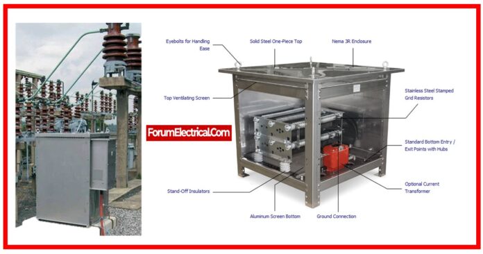
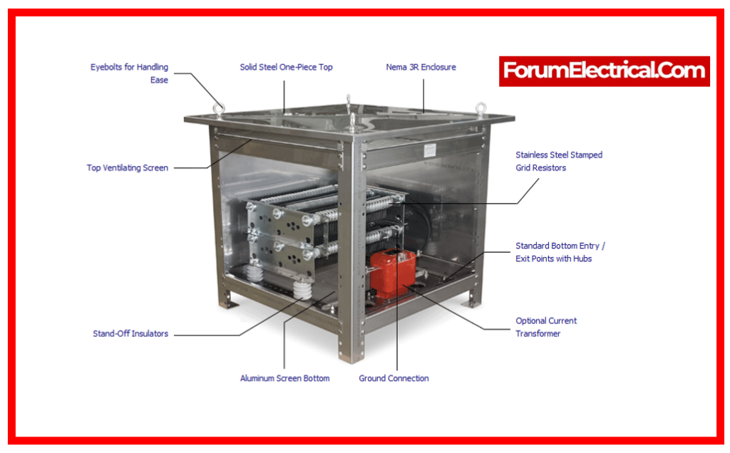
A Neutral Grounding Resistor (NGR) is a resistor that is installed between a system’s neutral point (such as a transformer, generator, or motor) and the ground. Its main function is to reduce the current flowing through the neutral line when a ground fault occurs.
In the field of electrical power distribution, ground faults can develop when a conductor’s insulation fails, allowing current to flow directly from the system to the earth. This current, if not managed, can become dangerously high, causing equipment damage and creating a safety risk.
The NGR is intended to mitigate these harmful consequences by limiting the fault current to a safe level.
It accomplishes this by raising the resistance in the line to ground, hence decreasing the current based on Ohm’s Law(I=V/R).
It permits a controllable amount of current to flow, sufficient for protective relay systems to detect the fault & take necessary measures, while avoiding a large, potentially harmful current.
Working Principle of Neutral Grounding Resistor
Ohm’s Law, which states that the current flowing through a conductor between two points is directly proportional to the voltage across the two points and inversely proportional to the resistance between them, is the fundamental law of electricity and the basis of the operation of a neutral grounding resistor (NGR).
With I standing for current, V for voltage, and R for resistance, this relationship can be expressed mathematically as I=V/R.
A system’s neutral point, such as the ground (earth), is connected to the NGR by means of a transformer, generator, or motor. Electrical energy is safely directed through this grounding connection.
As long as there is no potential distinction between the neutral point & ground, the NGR remains in a state of normal operation.
A potential difference generated & current starts flowing from the fault location towards the ground when an unintentional connection between an electrical system & ground happens during a ground fault condition.
There would be relatively small resistance in the path, thus if the system was directly grounded (i.e., no NGR), the fault current may rise to very high levels.
Along with posing a major safety danger, this enormous current could seriously harm the electrical equipment.
The NGR is relevant in this condition. The NGR assures that the fault current is restricted to a safe level by adding a sizable resistance into the grounding channel.
Ohm’s Law is the source of this; at a given voltage (V), increased resistance (R) results in a decrease in current (I).
In addition, protective relay systems can identify a ground fault and start the proper action, like isolating the problematic component of the system, because the NGR regulates the amount of fault current that flows.
By doing this, the NGR assists in reducing the risk to workers, lessen damage to electrical equipment, and improve the power system’s overall dependability.
How does a Neutral Grounding Resistor (NGR) Works?
NGR operates by decreasing the ground-fault current to a predefined level. With a properly built neutral grounding system, you may utilize both ungrounded and strongly grounded systems.
When we connect an NGR system between neutral & ground in a power system, it proceeds to provide ground fault protection by restricting ground-fault currents to safe levels.
As a result, it makes sure all electrical equipment in the electrical system is adequately secured. NGRs not only absorb a large amount of energy but also disperse it throughout the duration of the fault occurrence, ensuring that the temperature stays within limits.
Therefore, the design & selection of a NGR is extremely essential if you want to secure equipment and maintain personnel safety.
Function of Neutral Grounding Resistor in Power System
- The main function of an NGR in the power system is to control the excessive current flow caused by the line to earth fault.
- A fault current regulator serves as an NGR performs. By using resistance, it restricts the fault current.
- Consequently, because protection relays take some time to correctly isolate the power system, a high flow of fault current can quickly damage the conductor.
- In that period of time, NGR gets involved by controlling the abrupt fault current flow and transforming it into thermal energy.
- An additional tool for controlling the Earth Fault Relay is a neutral grounding resistor. The current that passes through NGR can be measured and monitored to achieve this. The earth fault relay trips the circuit if an earth fault exists.
- Protective equipment can be connected with the aid of the neutral grounding resistor because it is typically unable to function with a large current.
- So that the safety equipment does not need to run at a high current, the current can be decreased using an NGR. NGR also guards against insulation failure in electrical equipment.
- Arching grounded on ungrounded systems causes transient over-voltages, which is what causes the electrical equipment problems.
- Machine strains & circuits carrying fault currents & NGR are reduced in systems that are firmly grounded by mechanical stresses.
- Measurement of the fault current via neutral grounding transformers is also aided by an NGR.
- If a ground fault occurs, it can also function as an alarming system. Furthermore, it has sufficient tripping thresholds to aid in meticulous ground-fault detection.
Selection of NGR-Neutral Grounding Resistor
Neutral Grounding Resistor (NGR) selection is an essential step that must be carefully considered. Incorrect selection may result in insufficient protection and possible damage to the power system.
Here are the important elements to consider while choosing an NGR:
1). System Voltage
2). Fault Current
3). Fault Duration
4). Material & Construction
5). Requirements
6). Maintenance
1). System Voltage
The NGR’s voltage rating is determined by the system line-to-neutral voltage. For a three-phase system, this voltage is commonly calculated as the system voltage divided by the square root of three.

2). Fault Current
Determining the resistance value of the NGR requires knowing the desired ground fault current. This desirable value is frequently determined based on the fault detection capabilities of the system (or) other system protection requirements. The resistance value (R) is then determined using Ohm’s Law:
R = V/I
3). Fault Duration
The NGR should be able to withstand the heat created by the flow of the fault current for a particular time period without exceeding its thermal limits.
This duration is often determined by the projected time it will take for the protective mechanisms to isolate the fault.
4). Material & Construction
The resistor material, construction, and environmental impact are all important concerns. The material should be stable across a wide temperature range, & the architecture should allow for heat drainage. In addition, depending on the location and conditions of installation, the NGR might need environmental protection (such as an ingress protection rating).
5). Requirements
The NGR shall comply with all applicable industry safety and performance requirements.
6). Maintenance
The ease of maintenance, accessibility for frequent testing, and monitoring capabilities should all be considered.
Applicable Standards
IEEE 32, IEC 60137, EN ISO 1461, , IEC 60071, IEC 60529.
Advantages of Neutral Grounding Resistor (NGR)
- Neutral Grounding Resistors (NGRs) protect equipment by decreasing fault current during a ground fault, which minimizes damage and lowers repair costs.
- NGRs improve safety by decreasing the possibility of arc flash events and electric shock dangers.
- NGR assist to locate and isolate defects, reducing downtime.
- NGRs effectively stabilize phase voltages, resulting in a dependable and balanced system.
- Furthermore, they enable interim continuous functioning during a single line-to-ground fault, supporting uninterrupted service.
- NGRs provide essential protection, safety, & stability to electrical power systems, extending equipment life and ensuring continuous operation.
- NGR provides reliable, easy, selective safety.
- Losses might result from unplanned downtime.
Disadvantages of Neutral Grounding Resistor (NGR)
- During fault conditions, NGRs can generate a lot of heat, thus suitable ventilation (or) cooling systems are required to keep them from overheating.
- NGRs are intended to limit fault current for only a short time (usually a few seconds). Extended faults may cause heat damage to the resistor.
- Detecting low-magnitude ground faults in NGR-equipped systems can be more difficult than in systems with solid grounding.
- NGR systems require constant maintenance to function properly, which increases operational costs. The initial cost of installation can sometimes be rather costly.
- NGRs limit the system’s ability to handle larger fault currents, potentially limiting future flexibility in expansions or configuration.
- During fault conditions, NGRs can generate transient voltage fluctuations, which might harm sensitive equipment.
Applications of NGR
- NGRs are primarily used to prevent ground fault damage to electrical equipment. High fault currents can harm electrical components without an NGR. Transformers, cables, switchgear, & generators might be damaged, causing system downtime and high repair costs.
- Electrical system arc flashes create a serious safety danger. Flashovers occur when a substantial amount of electrical energy emerges across an air gap. NGRs limit fault current to lower arc flash energy, minimizing danger and severity.
- A ground fault can cause a specific amount of fault current to flow via NGRs, which protective relays can detect. These relays may then trip to isolate the malfunctioning part. In advanced systems, fault current flow can also locate the fault.
- An NGR grounds the system’s neutral point to near-ground potential. This stabilizes phase voltages during normal operation & unbalanced conditions.
- In some systems, especially industrial ones, it can be useful to allow service to continue during a single line-to-ground fault. The NGR limit’s fault current to a safe level, enabling temporary functioning until the fault is fixed.
- Electrical shock (or) arc flashes pose a substantial risk to persons and equipment.
- Electrical equipment can be damaged by high earth return currents.
- High earth return currents may disrupt your telecom equipment.
Testing of NGR
Routine Test
- Insulation resistance between the enclosure and the resistor.
- DC Resistance Measurement.
- Insulation test on resistor blocks.
- Thickness of galvanization &/or paint.
Type Test
- Temperature rise test.
- Protection degree test.
- Impulse voltage measurement (1.2 / 50 µs).
Special Test
- Resistance to alternating current.
- Seismic test.
- Insulation resistance test (Megger Test).
Difference Between NGR & NGT
NGR vs NGT
| NGR (NER) | NGT |
| NGR is a resistor that connects the neutral point of a power system to ground. | NGT is a transformer with the main winding connected to the power system’s neutral and the secondary winding connected to ground. |
| It limits the fault current that flows through the system’s neutral during a ground fault. | It delivers a low impedance path to ground for fault currents. |
| NGRs are commonly employed in low voltage systems & grounding systems when a high-resistance grounding approach is preferred. | NGTs are commonly employed in medium & high voltage systems when a low-resistance grounding approach is preferable or mandated by standards and regulations. |
You can also follow us on Facebook and Linkedin to receive daily updates.


