 system. Throughout the whole process of establishing standards, choosing components, and testing, this all-inclusive post assures dependability and efficiency in your industrial automation projects.)

- What is a Programmable Logic Controller (PLC)?
- Why do we need a PLC?
- 10 Steps to Design a PLC
- 1). Environmental Specifications
- 2). Grounding & Earthing
- 3). Safety Concerns
- 4). Networking
- 5). Field Devices and I/O Count
- 6). Grouping of Devices
- 7). Field Wiring by Voltage Level
- 8). PLC Program Complexity & Redundancy
- 9). Utilize an HMI
- 10). Maintenance
- PLC Programming Basics
What is a Programmable Logic Controller (PLC)?
A programmable logic controller (PLC) is a small computer that can accept data from input and generate operating instructions as its output. A PLC’s primary function is to control the functions of a system utilizing the underlying logic that it has been programmed.
PLCs (Programmable Logic Controllers) is common in industry today.
Proper PLC system design can give many years of service to a machine or process while also increasing efficiency & profitability for the company that owns it.
Why do we need a PLC?
PLCs can be “relay replacers,” allowing for logic, timing, & counting capabilities that could be difficult to achieve with separate components.
PLCs can execute math functions, calculating depending on external signals &/or HMI (human-machine interface) data.
VFDs (variable frequency drives) are an excellent example of PLC application.
Ethernet/IP or other fieldbus-based communication protocols can now connect PLCs to a large number of VFDs.
A significant amount of wiring can be avoided by utilizing the communications protocol.
PLC is a key component of industrial automation. PLCs fall underneath the L1 level of the industrial automation, where they process field IOs and operate according to the logic contained in them.
It is thus an important component since, without PLC, we cannot work at higher levels such as cloud networks (or) IoT because they cannot communicate with field equipment and collect data from them.
10 Steps to Design a PLC
Designing a PLC system requires an organized approach to ensure efficiency & effectiveness in managing industrial processes. From defining project requirements to selecting hardware & programming software, each step is important for getting the intended results.
This process typically consists of
- Analyzing system requirements,
- Developing the system architecture,
- Programming the logic,
- Testing and commissioning, and
- Establishing maintenance plans.
By methodically following these steps, engineers may create strong PLC systems that match the specific requirements of their applications, assuring smooth operation and increased productivity.
There are many steps, factors, and requirements to consider before selecting the most suitable PLC system.
1). Environmental Specifications
2). Grounding & Earthing
3). Safety Concerns
4). Networking
5). Field Devices and I/O Count
6). Grouping of Devices
7). Field Wiring by Voltage Level
8). PLC Program Complexity & Redundancy
9). Utilize an HMI
10). Maintenance
1). Environmental Specifications
All electrical equipment experiences some level of environmental design constraints. PLCs are also a form of electrical equipment, and their components are highly sensitive to environmental conditions.
So, it is essential to ensure that no damage is created by any anomalous surrounding effect. The PLC should be capable to perform the functions specified in the catalog.
Some basic environmental elements to consider include ambient temperature (during operation & storage), relative humidity, operational altitude, and mechanical stress, such as vibrations.
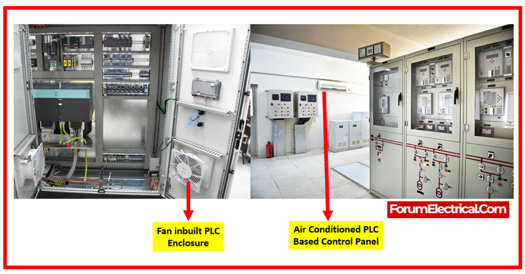
The PLC installed must fulfill the local environmental standards. When the temperature is outside the operational range, whether excessively hot or cold, it is recommended to use a hard-rugged PLC that meets the specified requirements.
When utilizing PLC in such an environment, it is possible to employ some supporting equipment such as fans, heaters, air conditioners, etc.
- Fans,
- Coolers,
- Air conditioners, &
- Pneumatic coolers
can be used to maintain a desired temperature in the enclosure inside. Consider installing panel heaters in outdoor or cold areas. To avoid runaway conditions and conserve energy, ensure that cooling (or) heating devices having thermostats installed.
Surge suppression devices should be employed to defend against both external surges that include lightning & utility switching disruptions, and also internal surges created by the plant’s electrical equipment.
2). Grounding & Earthing
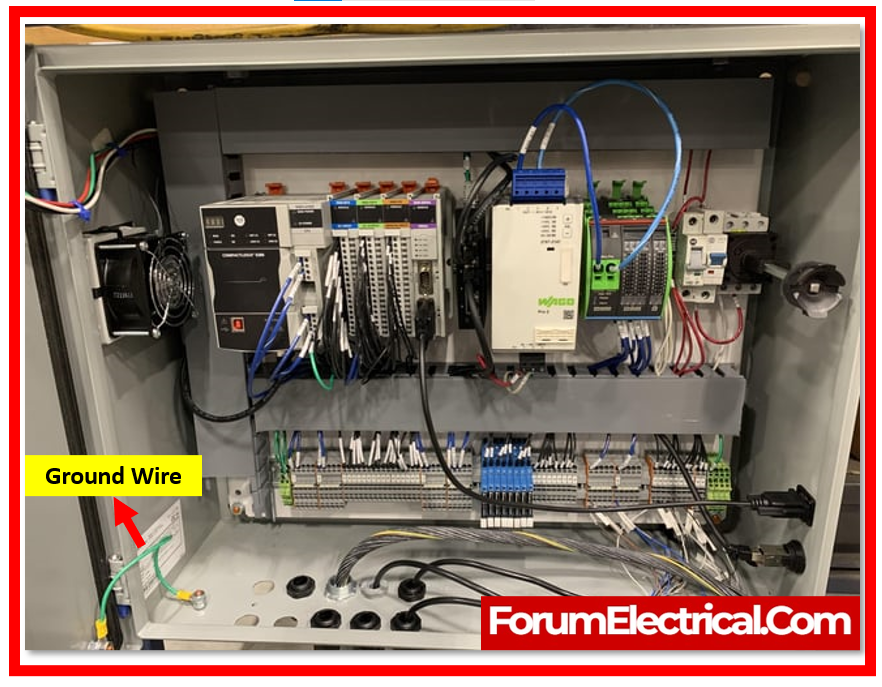
Grounding & earthing are essential parts of designing a PLC system. Improper grounding can lead to physical dangers, electrical device damage, & life loss.
Grounding points exist in both the power supply and the input-output terminals of a PLC.
When installing of the PLC panel, be assured that the ground is connected at every available point.
It is common to employ a
- Ground lug and
- Ground bar.
Scrape the paint from the subpanel where we will be installing the ground lug and bar. Make ensure that every device is grounded according to the manufacturer’s instructions.
There are two kinds of earthing in the PLC panel. They are called
- Instrument earth &
- Power earth.
The PLC input & output cards should be connected to instrument’s earthing. They must not be connected to the power earthing. It is important to note that the voltage between earthing & neutral must always be less than 0.5V.
3). Safety Concerns
In the design of PLC systems, safety is of utmost importance. In an industrial, a PLC will interact with numerous essential field devices. As a result, safety is an extremely significant consideration.
The first step is to conduct a hazard and operability analysis (HAZOP) for the machine/process. Once the HAZOP has been completed, safety devices are used to minimize or mitigate the hazard.
- Guarding,
- Operator safety,
- Light curtains,
- Protection from falling risks,
- Electrical shock, and
- Thermal issues (burns, open flames)
are all potential safety concerns.
The PLC must be set so that digital outputs are assigned to a hooter, tower lamp, fault lamp, & buzzer. This will notify the operator if there is any fault.
It is recommended that a safety study be conducted on-site to determine whether any environmental, mechanical, electrical, thermal, (or) chemical hazards exist. Safety PLCs are also accessible.
Some manufacturers provide safety PLCs, which include special safety functions built into the device. Safety relays are indicated for use with
- Emergency stop circuits,
- Light curtains,
- Safety mats,
- Guarding devices, and
- Interlocking switches.
Safety relays employ a dual-channel technique and provide better degrees of safety. They cannot be rapidly defeated.
These include safety integrity level functions for dealing with various types of IO and programming safety.
They can identify permutations & combinations of the failures and securely shut down the system.
Furthermore, depending on the process significance, several PLCs with varying scan times are possible.
4). Networking
A PLC have to manage with external communications with the third-party (or) same-party devices at some point in time.
We use a variety of protocols in communication with field devices, such as SCADA, to enable greater flexibility in data handling.
Communication may be sensitive to noise or other electrical disturbances, so it is essential to select a shielded cable.
In an Ethernet protocol, it is suggested to include an Ethernet hub switch in the panel, either managed or unmanaged. This is accomplished so that many individuals can benefit from the data.
Many systems have a 120V outlet and an Ethernet interface module on the exterior opening of the electrical enclosure.
These devices can be configured with a single or dual 120Vac outlet & an Ethernet port.
When performing system maintenance, you may plug in a laptop without having to find a nearby outlet.
Furthermore, it maintains the enclosure’s arc flash integrity by not requiring the door to be opened.
Ensure that the
- Network IP addresses,
- Subnet mask, and
- Gateway
are properly documented.
5). Field Devices and I/O Count
When selecting a PLC, the number of I/O’s & field instrument types has already been considered. To operate with field devices, you must understand voltage and current.
Based on this, the PLC & cabling length are determined.
It should be mentioned that it is always recommended to keep at least 20% spare in the IO counts. This allows for flexibility in the event of end-of-life IO additions.
If the distance between the PLC & the field device is greater, or if the PLC is to be located in a hazardous region,
- Barriers and
- Isolators
are provided within the panel.
Analog IOs require adequately insulated wires due to their susceptibility to noise.
4-20mA signals are widely utilized in analog circuitry. Use high-quality shielded wire; but be sure to follow the manufacturer’s wiring guidelines.
6). Grouping of Devices
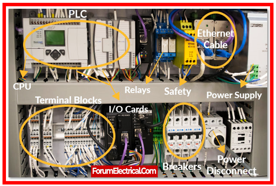
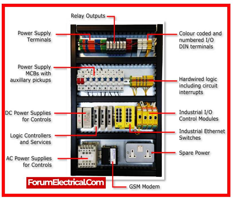
During the design phase of a PLC, the voltage level in PLC panel is used to group devices appropriately. This ensures that AC and DC equipment are separated, such as
- Circuit breakers,
- Relays,
- Terminal boards,
- Power supply, and
- Transformers.
It is recommended to maintain these groups distinct & not mix them. Also, the circuit breaker should not be kept near the PLC. It is preferable to maintain isolation between devices at the same voltage level.
As a result, troubleshooting will be simplified, and undesirable performance & noise in the panel may be reduced.
When AC and DC devices are separated and organized, the panel appears more appealing. It also gets easier to correctly identify each device.
7). Field Wiring by Voltage Level
In a PLC panel, AC & DC voltages coexist. When working with a field device that is energized by a separate power source, make sure you use the common point. Care must be taken to avoid mixing unwanted common field signals, as this may damage the PLC (or) the field device.
8). PLC Program Complexity & Redundancy
The redundancy factor should be considered when developing a PLC. The PLC must be picked appropriately. Furthermore, the PLC must be able to complete the work within the required scan time, memory, & redundancy.
9). Utilize an HMI
HMIs are affordable and provide a good perspective into the PLC functioning. Many companies suffer because they lack the necessary programming skills or PLC software.
- An HMI allows you to
- Change timer and counter settings,
- Monitor the status of internal bits & values,
- Modify analog values, and
- Do an array of other things.
Passwords can keep operators out of especially important places.
10). Maintenance
Keep electrical panels clean of dust, dirt, & other debris. Make sure the wiring is clean and the wire duct covers are in place.
Check and tighten all screw terminals on a regular basis. Do not overtighten all the terminals; snug is acceptable, but too tight can make problems worse.
If in uncertainty, follow the manufacturer’s torque recommendations.
Make sure the panel is labeled with
- Networking IP addresses,
- Fuse ratings,
- The name of the PLC software file, and
- Any additional information
that will help you service the machine.

PLC Programming Basics
The PLC’s CPU will execute two distinct programs. They are:
- Operating System
- User Program.
1). Operating System
- Handling of hot and warm restarts.
- Update and output the process image tablets of the input & outputs.
- Execute the user program.
- Detect and call interruptions.
- Manage the memory areas.
- Establishes connectivity between programmable devices
2). User Program
The user program is a collection of various functions that are necessary to complete an automated task.
This must be created by the user and downloaded to the CPU of PLC. The user software completes the following tasks:
- All conditions are initialized while starting the given work.
- Read and evaluate all binary & analog input signals.
- Specifying output signals for all binary & analog output signals.
- Interrupts and error handling
There are numerous PLCs ranging from minor to high-end PLCs. All PLC vendors provide their own software for programming and configuring the PLC hardware.
The PLC programming language differs according to the vendor. Certain manufacturers use the same programming languages, while others do not.
These languages are classified into 2 types. They are:
Textual language:
- Instruction List (IL) and
- Structured Text (ST).
Graphical language:
- Ladder Diagrams (LD),
- Function Block Diagrams (FBD), and
- Sequential Function Charts.
Graphical languages are chosen over text languages for programming PLCs because they have simpler and more convenient programming features.
Some necessary functions & functional blocks are included in the standard library of every PLC software.
The functional blocks include timers & counters, comparators, strings, as well as numeric, arithmetic, bit-shift, and calling functions.
Following the steps above will provide you with useful knowledge, whether you are a system designer (or) collaborating with a skilled in-house (or) third-party specialist.
Implementation will additionally assist you get many years of service out of your PLC system.