
Fundamental Importance of Transformer Windings
Transformer winding resistance testing is of fundamental importance.
Winding resistance measurements in transformers are important for the following purposes:
- Calculating the I2R component of conductor losses.
- Calculating winding temperature after a temperature test cycle.
- Used to analyze potential field damage.
Transformers are susceptible to vibration.
Problems or faults arise as a result of
- Faulty design,
- Assembly,
- Handling,
- Improper surroundings,
- Overloading, or
- Inadequate maintenance.
Measuring winding resistance ensures correct connections and shows no substantial mismatches (or) openings.
Many transformers include taps.
These taps allow you to increase or decrease the ratio by fractions of a percentage.
Any ratio change involves the mechanical contact movement from one position to another. These tap modifications will also be evaluated via a winding resistance test.
Irrespective of whether the configuration is wye or delta, measurements are taken phase to phase & compared to see if the readings are similar.
If all readings are within 1% of one another, they are acceptable. Keep considering that the test’s purpose is to check for significant variations in the windings as well as connections that are open.
The tests are not intended to reproduce the readings of the manufacturing device, which was tested in the factory under controlled conditions & maybe at different temperatures.
Transformer Characteristics
A transformer is a passive device that stores and delivers finite amounts of energy.

Practically all transformers use magnetic material to shape the magnetic fields that serve as a medium for transmitting energy.
The link between magnetic-field quantities & the electric circuits with which they interact is essential to describing the device’s functionality.
The magnetic material defines the size and capabilities of the machine, as well as creates constraints due to saturation and performance degradation.
A transformer is essentially made up of two (or) more windings connected by a mutual magnetic field. These windings are essentially wire coils that function as inductors.
Transformer properties can now be determined using simple formulas.
V = L (di/dt)
It should be emphasized that an abrupt change in inductor current necessitates a rapid change in the energy stored in the inductor, which necessitates infinite power at that time; infinite power does not exist in the real world.
The inductor current should not be permitted to jump from one number to another. If a test is made to open circuit a physical inductor along which a finite current flows, an arc will form across the switch.
This is useful in the automobile’s ignition system, but this is unlikely to occur during transformer winding testing.
The energy stored in an inductor with circulating current can be expressed by the following formula:
W (t) = 1/2 I2L
where
W (t) – Energy as a function of time
I = Current (A)
L = Inductance (H)
Before a specific current may flow (for testing reasons), this energy demand must be met, which suggests that some time will be required before the measurement may be taken. This time requirement solely pertains to charging time. Before taking a measurement, further time should be allowed for the current to stabilize.
The time necessary to take a reading is limited by the intrinsic time lag between applying a steady current and the core’s magnetization becoming stable.
Depending on the transformer’s size and structure, testing times might be relatively quick for tiny transformers or quite long for bigger, highly inductive transformers.
What is the resistance of the winding?
The resistance of a copper wire measured from one end to the other is known as winding resistance.
This measurement relates to Ohm’s law, which states that resistance (R) is equal to voltage (V) divided by current (I) in DC.
Testing Equipment
Before current digital electrical equipment, the Kelvin Bridge was employed.
- Batteries,
- Switches,
- Galvanometers,
- Ammeters, and
- Slidewire adjustments
were utilized to measure resistance.
Current regulators were built and installed between the battery & the bridge.
The regulator received a 12 volt dc input voltage from an automotive storage battery, and the output currents were varied in steps that matched the bridge’s maximum current rating on the ranges most commonly used on transformers.
The current regulator improves the speed and accuracy of bridge readings.
The approximately 11 volt availability was utilized to accelerate the early current increase and tapered off to around 5 volts just before the desired current was obtained and regulation get started.
When regulation commenced, the current remained essentially constant despite the inductance of the windings and fluctuations in battery voltage or lead resistance.
Testing periods have been significantly decreased thanks to contemporary microprocessor-based test equipment.
Digital meters provide direct readings, with automatic signals of when a valid measurement is available.
Some testers have 2 meters, which allow you to measure two resistances at the same time.
Caution: Because of the tremendous amount of energy that may be stored in an electromagnetic field, exercise caution prior to disconnection of the test leads from the transformer being tested.
Avoid removing the leads during the testing process, and always provide enough time to fully drain the transformer being tested. Large transformers can take many minutes to discharge.
New winding resistance testers now have indicators that show when it is safe to remove the leads.
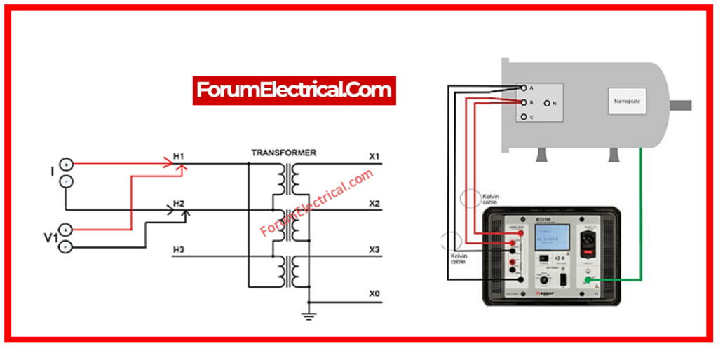
Principles of Operation
The basic principle is to inject a DC current across the winding to be tested, then measure the voltage drop across it.
Electrical testing equipment use dc current across the winding and an inbuilt standard current shunt.
After measuring both DC voltage dips, they are ratio and shown as resistance on front panel meter.
This method permits the lead resistance to be eliminated because the readout is independent of the current.
Additionally, no multiplication factors will be required while changing current ranges.
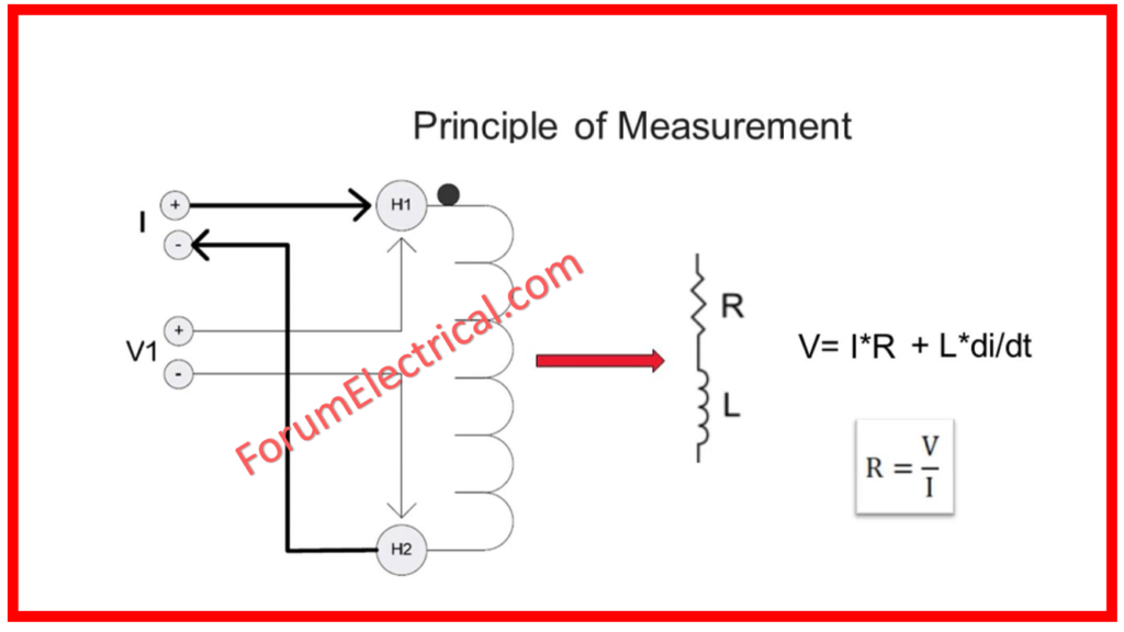
The DC current source should be exceedingly steady. Make sure to refer to the formula below for calculating the DC voltage across a transformer:
V = I x R + L (di/dt)
where
VDC – Voltage across the transformer winding.
I – DC current across the transformer winding.
R – Resistance of the transformer winding.
L – Inductance of the transformer winding.
di/dt -Changing value of current (ripple)
Assuming the tester has a highly stable current source (i.e., no ripple),
di/dt equals zero, and
the term L di/dt equals zero.
Tap Changers
Tap changers are classified into two categories:
- On-Load Tap Changers and
- Off-Load Tap Changers.
The on-load tap changer allows for sectional ratio changes when the transformer is in service. This means that the transformer ratio may be adjusted while power is still flowing through it. Voltage regulators are the most prevalent sort of on-load tap changer.
On-Load Tap Changer
- The resistance tester is beneficial for testing on-load tap changers since it may be left on while switching between taps.
- It enables the operator to conduct measurements fast without discharging and recharging the transformer for each tap.
- The winding resistance tester will re-balance after each tap change.
- If the tap is defective (open), or if the circuit is open for even a fraction of a second, the winding resistance tester will immediately enter discharge mode.
- This gives the operator a visible signal of a possible malfunction in the tap-changer via a panel light.
- The test set will not do any damage to the transformer under this open condition.
Off-Load Tap Changer
- This type of tap changer requires the tap changer to be discharged across tap changes.
- To change taps, the transformer must be taken out of service or disconnected from the load. This tap changer type can often go bad.
- Because the taps were accidentally changed while still in service, they moved faster than an on-load.
- The resistance tester will continue to work on this changer, but it must be discharged between tap changes.
Test Results
Winding resistance data are typically interpreted by comparing each resistance measurement to the resistance of the next neighboring winding at same tap.
If all readings are under one percent of one another, the specimen is deemed to have passed the test.
Comparisons can also be done with original factory-measured test data using temperature-corrected values, having taken into account that field resistance tests are not intended to reproduce the manufacturer’s test record.
The manufacturer’s test was most likely carried out in a controlled environment at the manufacture time.
Sample Test Data
Resistance values will be expressed as ohms, milliohms, (or) microhms based on the size of the transformer winding being tested.
The table below shows how test data for a basic 13,200-208/120V 3-phase transformer with 3 primary de-energized tap changer settings can be collected.
| Windings | Tap Position | Resistance (milliohms) |
| H1-H2 | 1 | 750.3 |
| H2-H3 | 1 | 749.8 |
| H3-H1 | 1 | 748.5 |
| H1-H2 | 2 | 731.8 |
| H2-H3 | 2 | 731.4 |
| H3-H1 | 2 | 729.4 |
| H1-H2 | 3 | 714.6 |
| H2-H3 | 3 | 714.3 |
| H3-H1 | 3 | 712.3 |
| X1-X0 | N/A | 0.355 |
| X2-X0 | N/A | 0.3688 |
| X3-X0 | N/A | 0.39 |
Safety
Although some inspections can be completed without de-energizing the transformer, winding resistance measurement does not constitute one of them. To ensure optimal worker safety, disconnect both the
- High-Voltage Lines &
- Low-Voltage Lines
from the transformer.
There should be a noticeable separation across the transformer terminals & the high and low voltage lines.
Conclusion
Transformers are extremely dependable devices that may last for a long period if properly maintained and serviced.
Transformer failures are typically severe, necessitating expensive repairs and extended downtime.
The most effective way to prevent transformer failure is to make sure that they are properly installed & maintained.
When testing a transformer, be sure to include the winding resistance test.
Modern self-contained devices make testing simple and reliable.
Keep meticulous notes of the resistance values found and compare them to previous readings for variations.