
- Types of Transformer Faults
- External Faults
- Power Transformer External Short Circuit
- Power Transformer Voltage Disturbance
- Power Transformer Under Frequency Effect
- Internal Faults
- Insulation failure between the coil winding and the earth
- Insulation failure occurs between phases
- Insulation failure between consecutive turns, often known as an inter-turn fault
- Fault in transformer core
- Magnetic Inrush Current
- Tank Faults
Transformers are significant components of power systems that are utilised at different voltage levels with capacities ranging from 1kVA to greater than 700 MVA.
Transformers are extensively used devices for magnetically transferring power from a circuit to another without physical interaction.
Any damage that occurs to this component causes the whole system to lose power. The transformer should be safeguarded against faults to prevent transformer failure, which might result in a large disruption in power transformation.
Transformer monitoring and the timely detection of faults in transformers are of utmost importance in new power systems.
This is because if these defects fail to be identified in time, the transformer’s lifespan may be limited, it may be disconnected, or both.
Types of Transformer Faults
- External faults and
- Internal faults
are the two types of transformer faults.
External Faults
The term “external faults” refers to problems that arise from occurrences that take place outside the transformer itself and are often not preventable by maintenance. The transformers are susceptible to damage from the environment, such as lightning strikes and other forms of harm that cannot be avoided.
The most common problems that arise in exterior of a power transformer are,
- Power Transformer External Short Circuit
- Power Transformer Voltage Disturbance
- Power Transformer Under Frequency Effect
Power Transformer External Short Circuit
A short circuit in an electrical power system may occur in two (or) three phases. Fault current (%) is usually high.
It is determined by the voltage that has been short-circuited as well as thecircuit impedance prior to the fault location.
The fault feeding transformer having copper losses increases suddenly. Transformer internal heating is caused by increasing copper loss.
Transformers are mechanically stressed by strong fault currents.
During the initial cycle of symmetrical fault current, the mechanical stresses are at their peak.
Power Transformer Voltage Disturbance
There are two types of high voltage disturbances in power transformers.
1). Transient Surge Voltage
2). Power Frequency Over Voltage
1). Transient Surge Voltage
High voltage & high frequency surges in the power supply may occur as a result of any of the following causes:
- If the neutral point is isolated, arcing ground occurs.
- Changing the functioning of various electrical devices.
- Atmospheric lightning strike.
Whatever the reason of the surge voltage, it is, after all, a travelling wave with a high and steep wave shape as well as a high frequency.
This wave travels through the power system’s electrical network and, when reaching the power transformer, causes the insulation between turns close to the line terminal to fail, potentially resulting in a short circuit between turns.
2). Power Frequency Over Voltage
There is always the possibility of system overvoltage owing to the unexpected separation of a big load.
However, the amplitude of this voltage is more than its typical level, the frequency remains the same. Overvoltage in the system increases the stress on the transformer insulation.
Asknown, higher voltage induces a corresponding rise in working flux.
V = 4.44Ø f T
V ∞ Ø
As a result, there is an increase in iron loss & a correspondingly high rise in magnetising current.
The increased flux is directed from the transformer core to the transformer’s other steel structural elements.
Core bolts, which ordinarily transport minimal flux, may be exposed to a high component of flux redirected from the core’s saturated area beside.
Under such conditions, the bolt may get quickly heated, destroying both its own and winding insulation.
Power Transformer Under Frequency Effect
Since the number of turns in a winding cannot be changed,
Voltage,
V = 4.44Ø f T
V ∞ Ø
Therefore,
Ø∞ V/f
It is easy to see from this equation that a reduction in frequency in a system would increase the flux in the core, with effects that are similar to an overvoltage condition.
Internal Faults
The primary faults that occur within a power transformer are classified as follows:
- Insulation failure between the coil winding and the earth.
- Insulation failure occurs between phases.
- Insulation failure between consecutive turns, often known as an inter-turn fault.
- Fault in transformer core.
- Magnetic Inrush Current
- Tank Faults
Insulation failure between the coil winding and the earth
1). Internal Earth Faults within a Star Connection Winding to the Neutral Point and Earthed via an Impedance
As the voltage (V) at the point depends on the number of winding turns that intersect the neutral and fault points and the fault current in this condition is proportional to both the earthing impedance value and the distance between the fault point and neutral point.
More turns imply more turns under the distance between the fault point and the neutral point, which results in a greater voltage between the neutral point & fault point and a larger fault current.
So, in simple terms, it can be claimed that the distance between the fault point & neutral point, together with the earthing impedance value, affect the value of fault current.
The leakage reactance of the section of the winding that is located between the fault location and neutral also influences the fault current.
But since it is in series with a considerably larger earthing impedance, which is relatively low in comparison, it is simply ignored.
2). Internal Earth Faults within a Star Connection Winding and Solidly Earthed Neutral Point
The optimal earthing impedance in this situation is zero. The amount of winding leakage reactance that crosses the transformer’s defective point & neutral point determines the fault current.
The distance in the transformer between the neutral point & fault point affects the fault current as well. The number of winding turns that pass through the defective point and neutral point determines the voltage across the two places.
Therefore, in a star-connected winding with a properly earthed neutral point, the distance between the faulty point and neutral point as well as the leakage reactance of the winding are the two key determinants of the fault current.
However, the location of the winding defect affects the leakage reactance of the winding in a complicated way. The fault current is higher for the fault closest to the neutral end because it can be observed that the reactance falls very quickly for fault points towards the neutral.
Since the reactance that opposes the fault current is similarly low at this point and the voltage that is accessible to the fault current is low, the value of fault current is sufficient.
As observed, the voltage applicable for fault current is high at the fault point distant from the neutral point, but at the same time, the reactance provided by the winding part between the fault point & neutral point is high.
The fault current maintains a high level across the winding. In simple terms, regardless of where the fault is on the winding, the fault current maintains a very high magnitude.
Insulation failure occurs between phases
In the transformer, phase-to-phase faults are quite uncommon. In the condition that such a malfunction does take place, it will result in the generation of a significant current, which will trigger both the over current relay on the main side and the differential relay.
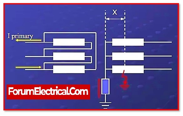
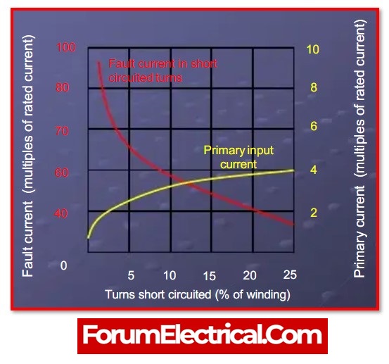
Insulation failure between consecutive turns, often known as an inter-turn fault
Due to a lightning surge on the transmission line, a power transformer linked to an electrical high voltage transmission system is extremely probable to be exposed to large magnitude, steep slope and high frequency impulse voltage.
The voltage strains between winding turns increase to the extent that they cannot be sustained, resulting in insulation breakdown between inter-turns in certain places.
The transmitted surge voltage also stresses the LV winding. A substantial proportion of power transformer failures are caused by a defect between turns.
Inter turn faults may also develop as a result of mechanical stresses between turns caused by an external short circuit.
Fault in transformer core
If any section of the core lamination gets damaged, or if the core lamination is connected by any electrically conducting material that allows sufficient eddy current to flow through it, this portion of the core overheats.
When the insulation on bolts (used to tighten the core lamination together) breaks, sufficient eddy current flows through the bolt, producing overheating.
This lamination & core bolt insulation breakdown creates considerable local heating. Although local heating generates extra core loss, it does not cause a perceptible change in input & output current in the transformer, therefore these faults are not detectable by a standard electrical protection mechanism.
It is preferable to identify the transformer core’s local overheating conditions before a catastrophic problem arises.
Excessive overheating causes the transformer insulating oil to break down, allowing gases to escape. These gases accumulated in the Buchholz relay, triggering the Buchholz alarm.
Magnetic Inrush Current
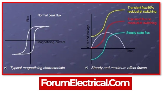
The core flux wave peak values depend on the residual flux and the time of switching when a transformer is turned on at any point during the supply voltage wave. Core saturation will act as a limiter on the flux peak value, which will be greater than the comparable steady-state value.
If the transformer is turned on while the supply voltage is zero, magnetic inrush occurs. The differential relays for protection of the transformer is used to prevent tripping owing to the magnetising inrush current. To avoid tripping caused by significant inrush currents, a variety of techniques depending on the harmonic characteristics of the inrush current are utilised.
Tank Faults
Tank malfunctions that lead to the loss of oil lower the insulation levels of the windings and cause abnormally high temperature rises.