 Readings Factors")
- Factors Affecting Insulation Resistance (IR)
- Type of Insulating Material Utilized
- Environmental Conditions
- Age of Insulation
- Voltage Level
- What causes Low Insulation Resistance Readings?
- Factors Affecting Insulation Resistance (IR) Readings
- Temperature and Humidity
- Time-Dependent Current Components
- Capacitance Charging Current
- Absorption Current
- Conduction (or) Leakage Current
- Time-Resistance Relationship
- Calculator
Factors Affecting Insulation Resistance (IR)
Insulation resistance is an important aspect to consider while assuring the safety of electrical systems. Insulating resistance is a measurement of how well the insulating material surrounding electrical conductors resists the flow of the electric current.
Insulation resistance is also affected by many other types of factors, including
- Type of insulating material Utilized
- Environmental Conditions
- Age of Insulation
- Voltage Level
under which the electrical system is installed.
Understanding these characteristics is essential for ensuring electrical safety in both household and industrial settings.
Type of Insulating Material Utilized
Different insulating materials can have varying degrees of resistance to electrical current. Rubber insulation, for example, can handle high voltages but is unsuitable for damp conditions.
PVC insulation, on the other end, can be more moisture-resistant but unsuitable for high-temperature applications.
Environmental Conditions
- Temperature,
- Humidity, and
- Chemical exposure
can all have an impact on insulating resistance.
Ex: High humidity might cause moisture to build on the insulation’s surface, reducing resistance.
Similarly, exposure to chemicals that include acids or solvents can damage the insulation material, resulting in reduced insulation resistance.
Age of Insulation
The quality of insulation material can decline over time as a result of exposure to environmental elements or wear and tear.
This can reduce insulating resistance, increasing the risk of electric shock (or) fire hazards.
Regular checking and repair of electrical systems may assist to identify and replace deteriorating insulation.
Voltage Level
The voltage level of electrical system may also impact insulating resistance. Higher voltage systems often require more insulating resistance to avoid electric shock dangers.
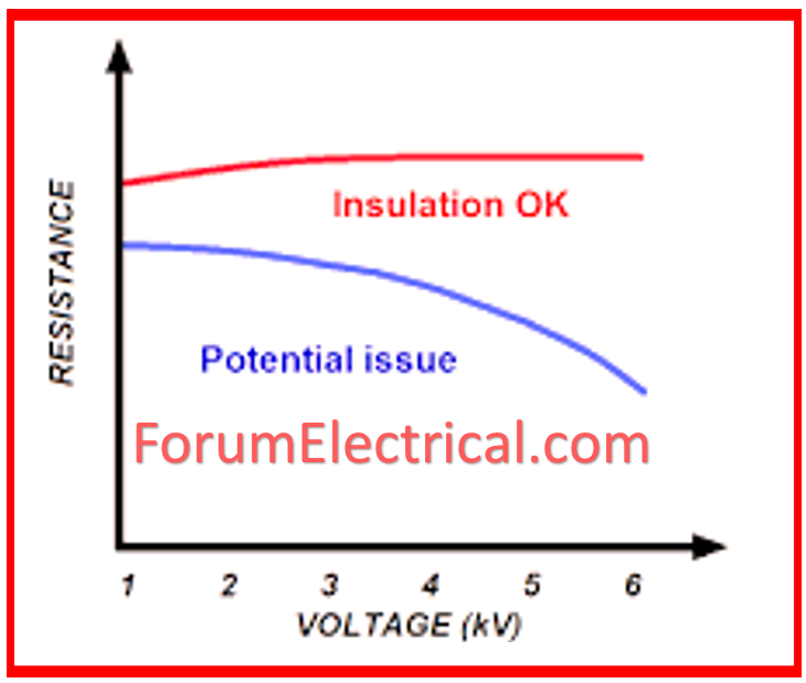
As the voltage increases, the insulation material should be able to tolerate greater levels of electrical stress.
What causes Low Insulation Resistance Readings?
Actual resistance ratings can vary based on factors such as the insulation’s temperature or moisture content.
Factors Affecting Insulation Resistance (IR) Readings
Several factors influence the measured insulation resistance (IR) readings, which must be understood while doing insulation resistance testing.
One of the most important ideas to remember is Ohm’s law (R = V/I), which connects resistance (R) to voltage (V) & current (I).
Here, we’ll look at how various factors influence the current that flows through insulation and, as a result, insulation resistance measurements.
- Temperature and Humidity
- Time-Dependent Current Components
- Capacitance Charging Current
- Absorption Current
- Conduction (or) Leakage Current
- Time-Resistance Relationship
Temperature and Humidity
Temperature
The insulation temperature can affect its resistance. Resistance often reduces when temperature drops or moisture content rises.
Humidity
High humidity levels might lead to a lower resistance path for electricity in insulation.
Time-Dependent Current Components
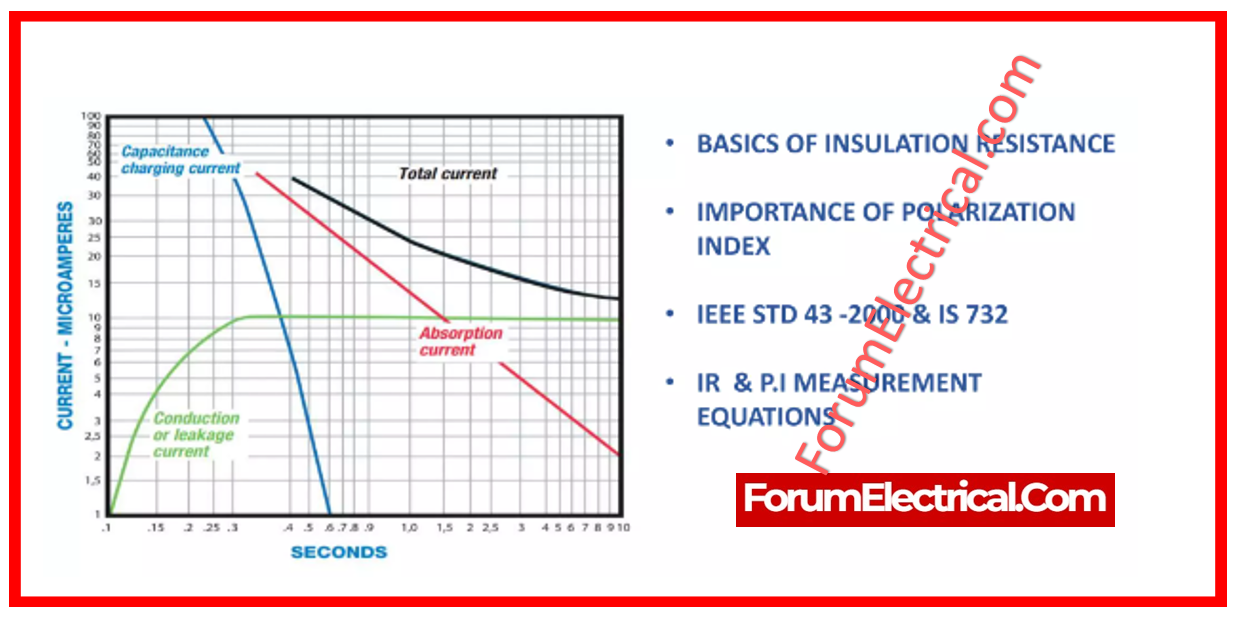
Whenever measuring insulation resistance, it’s important to remember that the current via insulation consists of three independent components, each with its own characteristics:
- Capacitance Charging Current
- Absorption Current
- Conduction (or) Leakage Current
Capacitance Charging Current
This current is initially strong but eventually reduces as the insulator charges to full voltage. It’s similar to how water flows in an irrigation hose if you initially turn on the faucets.
This component diminishes quite fast as the device under test charges. Larger equipment with higher capacitance might require longer to charge.
Following the test, it is important to discharge the accumulated energy by short-circuiting & grounding the insulation. Always follow this safety precaution.
Absorption Current
Absorption current reduces gradually and is determined by the insulation material.
Like capacitance charging current, it start high and gradually drops. The rate of decline is dependent on the insulation material.
At the completion of a test, it takes about 4 times as long to release the stored energy as it did to apply voltage.
Conduction (or) Leakage Current
A good insulation must have a stable leakage current that does not change with the applied voltage.
This is a modest, nearly constant current that passes through and across the insulation.
Any increase in leakage current over time indicates a potential problem and should be investigated.
Time-Resistance Relationship
The sum of all three of these components represents the overall current flowing across the insulator.
This current may be measured directly with a micro-ammeter (or) in megohms (MΩ) at a certain voltage with a Megger instrument (ohmmeter).
The total current is proportional to the time of the voltage applied.
In theory, Ohm’s Law (R = V/I) applies only to indefinite time (which is impracticable).
In practice, you get a noticeable resistance value that is useful for diagnostic purposes.
Calculator
Insulation Resistance in Excel: Simplifying Calculations for Safer System


 measurements. Discover how temperature, humidity, insulation material, age, and electrical stress affect IR values, ensuring maximum electrical safety and performance.)