
- Potentiometer Pin POut
- How to Choose a Potentiometer?
- Potentiometer Symbolic Representation
- Requirements for the selection (or) Setting-up of Potentiometer
- Components of the Potentiometer
- Construction of the Potentiometer
- Working Principle of the Potentiometer
- Types of Potentiometer
- Characteristics of the Potentiometer
- Potentiometer Voltage Measurement
- Sensitivity of the Potentiometer
- Potentiometer vs Voltmeter
- Rheostat vs Potentiometer
- Advantages of the Potentiometer
- Disadvantages of the Potentiometer
- Applications of the Potentiometer
- Summary
A cell’s internal resistance may be determined by using an electric device called a potentiometer to measure the electromotive force, or EMF, of a particular cell. In addition to that, the EMFs of various cells may be compared with its support. In a large number of conditions, it may also serve the function of a variable resistor.
These potentiometers are used in large numbers in the production of electronic equipment that provides a method for altering electronic circuits in order to generate the desired outputs. The purpose of this equipment is to give the ability to performing accordingly. Despite this, the most apparent use for them would have to be the volume controls seen on radios & other electrical equipment that is used to play music.
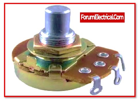
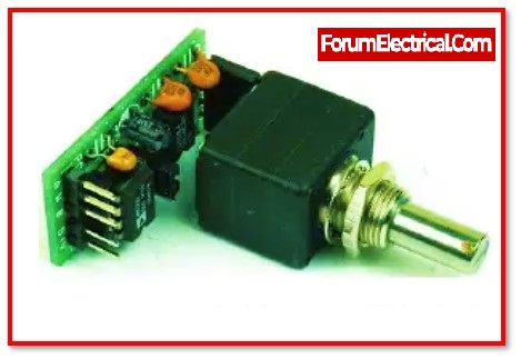
Potentiometer Pin POut
These potentiometers can be found in a wide range of types and have three leads. These components are simply put on a breadboard for prototyping. This potentiometer has a knob on top that is used to modify its value by turning it.
- Pin1 (Fixed End): This fixed end1 may be connected to one end of the resistive path.
- Pin2 (Variable End): This variable end may be connected through connecting it to the wiper to give changeable voltage.
- Pin3 (Fixed End):The additional fixed end can be connected by linking it to the resistive path’s opposite end.
How to Choose a Potentiometer?
Potentiometers are also referred to as POTs or variable resistors. These are employed to provide variable resistance by simply turning the potentiometer knob. This may be classified based on two major parameters:
- Resistance (R-ohms) and
- Power rating (P-Watts).
The potentiometer resistance, rather than its value, determines how much resistance it provides to the current flow.
When the value of resistors is large, the current flow is reduced. 500Ω, 1KΩ, 2KΩ, 5KΩ, 10KΩ, 22KΩ, 47KΩ, 50KΩ, 100KΩ, 220KΩ, 470KΩ, 500KΩ, 1MΩ are some of the potentiometers.
Resistors are classified mostly based on how much current they allow to pass through them, which is referred to as power rating.
Since a potentiometer has a power rating of 0.3W, it can only be used in low-current circuits.
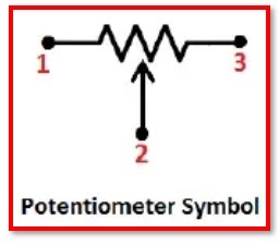
Potentiometer Symbolic Representation

For the purpose of depicting a potentiometer, two symbols are often employed. One is more common in America, whereas the other is an international standard sign for potentiometers. The American standard has zig-zag lines with 3 terminals separated by two straight lines. A rectangular box with 3 terminals set between two straight lines is included in the international standard.
Requirements for the selection (or) Setting-up of Potentiometer
Potentiometers are available in a range of forms & sizes, & their selection is dependent on particular needs such as:
- The requirements of the Structure
- Characteristics of Resistance to Change
- Choose a potentiometer depending on the application’s requirements.
- Find the settings according to the requirements of the circuit.
Components of the Potentiometer
Different components comprises of a Potentiometer,
1). Galvanometer
2). Ammeter
3). Jockey
4). Wire
5). Rheostat
1). Galvanometer
A device that can either detect the existence of a tiny current or measure the magnitude of the current that is present.
2). Ammeter
It is type of electronic equipment or an instrument, but either way, it is used to measure the amount of electric current that is flowing throughout an electric circuit.
3). Jockey
Whether it’s a wire potentiometer (or) a Wheatstone bridge, this is a pointed metal contact that’s utilised to ensure precise contact.
4). Wire
Potentiometer wire is often made out of alloys such as constantan or manganin since these materials have high specific resistance & a low temperature coefficient respectively.
5). Rheostat
To regulate the flow of current, this component, which is a variable resistor, is used. These components allow the resistance of a circuit to be varied without causing any disruptions.
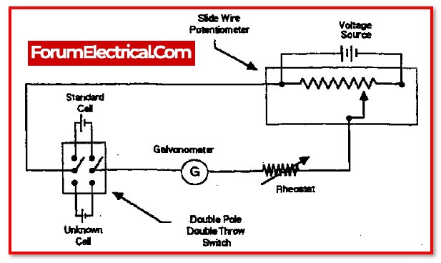
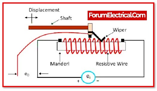
Construction of the Potentiometer
A potentiometer consists of a long wire with a consistent cross-sectional area. Typically, constantan or manganin comprise the wire. The wire can be divided into several sections, and each component is connected to the end focus by a substantial metallic strip.
Typically, copper strips will be used. The length of each wire is 1m. Nearly all of the time, there will be 6 wire pieces, totally 6 metres in length. The wire’s length often varies between 4 and 10 metres. The potentiometer’s accuracy improves with increasing wire length.
One end of the main circuit is taken up by the terminal of a different cell whose EMF E needs to be measured, & the cell terminal’s other end is connected through the galvanometer G to any point along the resistance wire.
Working Principle of the Potentiometer
If a wire has a constant current running through it and a uniform cross-sectional area, then the potential drop at any point along the wire is directly proportional to the wire’s length.As long as there is a voltage differential (potential difference) between any two nodes, an electric current will flow.
The modern potentiometer wire is a uniformly cross-sectioned, high-resistance (ρ) wire. This indicates that the resistance is the same all the way down the wire.
Currently, the cell phone’s high electromotive force terminal (V, ignored) as the driver cell (or0 the voltage source. Let I represent the current passing through the potentiometer and R represents resistance.
using Ohm’s law:
V = IR
Also, Resistance described as,
R = ρL/A
Thus,
V = I ρL/A
Since the rheostat maintains a constant value for the current I, ρ and A are also constant.
So,
L ρ/A = K
Where,
K – constant
The result is that
V = KL
Consider that the EMF of the driver cell is measured and then another cell, E, with a lower EMF has been added to the circuit. Consider EMF as an example. Let’s consider that after x lengths of potentiometer wire, the potentiometer is now represented by the letter E.
E = L ρx/A= Kx
Since the potential difference is zero when this cell is connected to the right length (x) in the circuit shown above and no current will flows through the galvanometer.
Therefore, the galvanometer G shows no detection. In this condition, x is the length of the null point. With the constant K & the length x , the problem can be solved. The unknown EMF’s position will finally be determined.
E = L ρx/A = K x
Second, assuming that the first EMF cell, E1, possesses null point at length L1, and the second EMF cell, E2, possesses a null point at length L2, allows us to compare the EMF of the two cells.
Then,
E1/E2= L1/L2
Types of Potentiometer
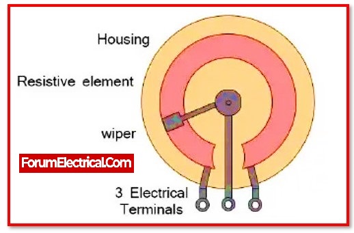
In addition, a potentiometer is often referred to as a pot. There are three terminal associations on these potentiometers.
The other two terminals are connected to a reasonable obstacle track, while one terminal is connected to a sliding contact known as a wiper. Either a straight sliding control (or) a rotating “wiper” contact may be used to move the wiper along the resistive track. The essential actions of turning & direct controls are comparable.
The single turn rotational potentiometer is the most used type of potentiometer. This type of potentiometer is often used in many applications, including sound volume-control (logarithmic form). Potentiometers are constructed from a variety of materials, such as metal film, conductive plastic, carbon structure, and cermet.
1). Rotary Potentiometer
2). Linear Potentiometer
3). Mechanical Potentiometer
4). Digital Potentiometer
1). Rotary Potentiometer
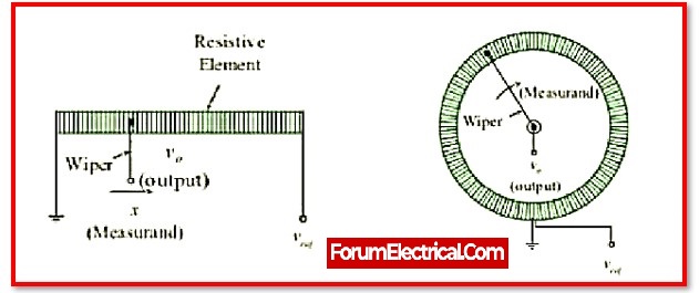
These potentiometers, in which the wiper moves circumferentially, are the most well-known type. These potentiometers are mostly used to provide a small number of circuits with changing voltage. The volume regulator of a radio semiconductor, where pivoting handle regulates the current stock towards the intensifier, serves as the greatest example of this rotating potentiometer.
This particular type of potentiometer has two terminal connections where a semi-roundabout obstacle may be placed predictably. Additionally, it retains a terminal for the center that is connected to the opposition using a sliding contact connected by a turning handle. Turning the handle over the barrier in the shape of a half-roundabout will move the sliding contact.
The two contacts of blockage and sliding may be used to get the voltage. Wherever it is necessary to control level voltage, these potentiometers are used.
2). Linear Potentiometer
The wiper in these types of potentiometers moves in a straight line. alternatively known as a slide pot, slider, (or) fader. This potentiometer functions similarly to the rotating type, however the sliding contact here essentially switched on the resistance directly. The two terminals of the resistor are connected across the voltage source. To use a method connected to the resistor, the resistor’s sliding contact may be moved.
The resistor’s terminal is connected to the slide, which is connected to one of the circuit’s yield completions, and another terminal is connected to the other yield completion. Most often, this kind of potentiometer is used to measure the voltage in a circuit. It is used in sound and music equaliser mixing systems as well as to measure the internal resistance of battery cells.
3). Mechanical Potentiometer
Potentiometers come in a variety of types, but mechanical ones are the ones that are used to physically adjust the blockage as well as the device’s output. However, a computerised potentiometer is used to adjust the resistance naturally based on the current state.
This type of potentiometer functions just like a potentiometer, but its obstruction may be altered via more sophisticated communication protocols like SPI and I2C rather than by simply turning the handle.
Because of its POT moulded design, these potentiometers are referred to as POT. Three terminals—I/P, O/P, and GND and as well as a handle are included in it. This handle pivots in two directions and also clockwise and anticlockwiseto act as a control to restrain the opposition.
Computerised potentiometers have a fundamental drawback in that they are fundamentally affected by numerous environmental conditions including dirt, dust, humidity, and so forth.
Advanced Potentiometers (digi-POT) were used to overcome these disadvantages. These potentiometers function normally even when exposed to residue, dirt, or moisture.
4). Digital Potentiometer
Advanced potentiometers, sometimes known as digi-POTs (or) variable resistors, are used with microcontrollers to operate basic indicators. These potentiometers provide an adjustable o/p opposition based on cutting-edge data sources. These are also known as RDACs (resistive advanced to-simple converters) on a regular basis.
Instead of via mechanical development, modern signals should be able to regulate this digit.
One switch that is connected to the output terminal of the advanced potentiometer is included into each step of the resistor stepping stool. Through the chosen venture over the stepping stool, the magnitude of the obstructing in the potentiometer is not fixed. For the most part, these methods are shown with a little respect. 256 steps are equal to 8 pieces.
For flagging, this potentiometer makes use of cutting-edge protocols like I2C or, in any event, the SPI-Bus (Serial Peripheral Interface). Since the majority of these potentiometers have essentially unstable memory, they don’t remember when they were turned OFF and their last location can be saved by the FPGA (or) microcontroller to which they are connected.
Characteristics of the Potentiometer
A potentiometer’s characteristics include the following.
- It is very accurate since it attacks the evaluating technique rather than the method of redirection to determine the unknown voltages.
- It determines that the equilibrium point is incorrect in any situation, hence no power for measurement is required.
- Due to there is no current progression across the potentiometer as it is adjusted, the potentiometer is free of source obstruction.
- This potentiometer’s key characteristics are the objective, tighten, checking codes, & bounce on/jump off opposition.
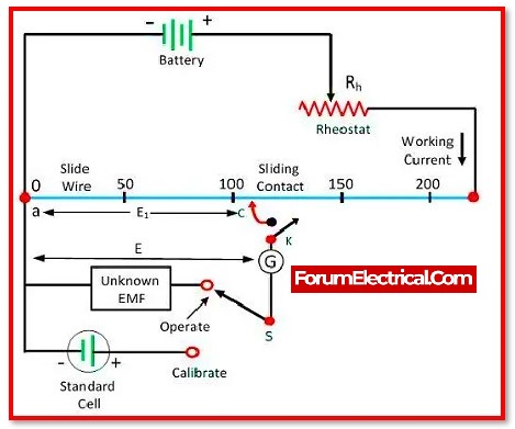
Potentiometer Voltage Measurement
Voltage measuring with a potentiometer in a circuit is a basic concept. The rheostat in the circuit must be changed, and the current flow through the resistor may be regulated such that an exact voltage is lowered for each unit length of the resistor.
Connect one end of the branch to the resistor’s starting point, while the other end may be connected to the resistor’s sliding contact through a galvanometer. And then slide the sliding contact over the resistance until the galvanometer shows zero deflection.
Once the galvanometer approaches zero, must record the position reading (reading value) on the resistor scale and use that to calculate the voltage in the circuit. Let users can alter the voltage for every length of the resistor to have a better understanding.
Sensitivity of the Potentiometer
Potentiometer sensitivity is defined as the smallest potential variation computed using a potentiometer.
Its sensitivity is mostly determined by the potential gradient value (K). Whenever the potential gradient value is said to be low, the potentiometer’s capability to compute potential differences is reduced, and the potentiometer’s sensitivity increases.
As a result, for any given potential dissimilarity, increasing the length of the potentiometer may improve its sensitivity. The sensitivity of the potentiometer may also be raised for the following reasons.
- By increasing the length of the potentiometer
- By reducing the flow of electricity through the circuit using a rheostat
- Both techniques will aid in lowering the potential gradient and increasing resistivity.
Potentiometer vs Voltmeter
| SL NO | Potentiometer | Voltmeter |
| 1 | The potentiometer has a high and infinite resistance. | The voltmeter’s resistance is high and restricted. |
| 2 | The current is not drawn directly from the emf source by the potentiometer. | The voltmeter takes a tiny current from the emf source. |
| 3 | When the potential disparity equals the definite potential difference, it may be determined. | When the potential difference is smaller than the exact potential difference, it may be measured. |
| 4 | It has a high sensitivity. | It has a low sensitivity. |
| 5 | It just measures emf and not potential difference. | It is a multipurpose device. |
| 6 | It is determined via the zero deflection approach. | It is determined by the deflection method. |
| 7 | It is utilised to calculate emf. | It is utilised to measure the terminal voltage of a circuit. |
Rheostat vs Potentiometer
| SL NO | Rheostat | Potentiometer |
| 1 | It has two terminals points. | There are three terminals. |
| 2 | It just has a single turn. | It features both a single and multiple-turn. |
| 3 | It is linked in series by the Load. | It is linked in parallel by the Load. |
| 4 | It regulates the current | It regulates the voltage. |
| 5 | It is linear. | It is both linear and logarithmic. |
| 6 | Carbon disc & metallic ribbon were utilised to create the rheostat. | Graphite is the substance used for making the potentiometer. |
| 7 | It is used in high-power applications. | It is used in low-power applications. |
Advantages of the Potentiometer
- As it employs the zero reflection method, there is no risk of error.
- Normalisation should be simply attainable by using an ordinary cell.
- It is used to measure small emfs since they are very sensitive.
- To attain accuracy, the potentiometer length may be increased according on the need.
- When the potentiometer is used in the circuit for estimate, it does not drain any current.
- It is used to calculate the inward blockage of a cell in the same way as the e.m.f. of two cells is calculated, however it is impossible to do so using a voltmeter.
Disadvantages of the Potentiometer
- The usage of a potentiometer is not valuable.
- The cross segmental space of the potentiometer wire should be dependable, thus this is essentially nonsensical.
- The wire temperature should remain constant throughout the trial, although this is difficult due to the current flow.
- The main disadvantage is that it requires enormous force to operate its wiper (or) sliding contacts. The wiper has disintegrated as a result of its development. As a result, the transducer’s life is reduced, and data transmission capacity is limited.
Applications of the Potentiometer
There are several distinct applications in which potentiometers are used that are:
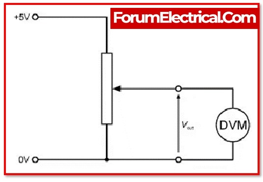
1). Potentiometer as a Voltage Divider
2). Audio Control
3). Television
4). Transducers
1). Potentiometer as a Voltage Divider
A voltage divider may be established by applying a predetermined input voltage across the potentiometer’s two ends. This allows for the output voltage, which is located at the slider, to be manually adjusted. Following is a calculation that may be used to get the load voltage across RL:
VL= R2RL x[ VS/(R1RL + R2RL + R1R2)]
2). Audio Control
One of the most common applications for modern low-power potentiometers is in audio control devices.
Examples of this use include sliding potentiometers. Both sliding potentiometers (also known as faders) & rotating potentiometers (also known as knobs) are used often in the attenuation of frequencies, the control of volumes, and other aspects of audio signals.
3). Television
Potentiometers were used to adjust many aspects of the image, including its brightness, contrast, & colour response.
A potentiometer, also known as a multi-vibrator, was often used in order to make adjustments to the “vertical hold,” which had an effect on the synchronisation between the image signal that was received and the internal sweep circuit of the receiver.
4). Transducers
Adjusting either the blockage or the voltage corresponds to adjusting the amount of body that is removed.
As a result, the fluctuation in voltage demonstrates that the body has been removed. The estimate of translational and rotational dislodging may both be accomplished with the support of technology.
These potentiometers are also referred to as resistive potentiometers due to the fact that they operate in accordance with the principle of opposition. For example, the shaft rotation may point to a certain point, & the voltage division proportion might be adjusted such that it corresponds to the cosine of the point.
Summary
A potentiometer is an electrical instrument that is often used for determining the difference in potential between two points in a circuit. It is also possible to use it to determine the EMF of a specific cell or to compare the EMFs of two cells.
In addition to this, we may utilise it to determine the resistance found inside the system. Because it does not need any current from the circuit, the reading it provides is more accurate than the reading a voltmeter would provide.
It is made up of a lengthy wire (manganin or constantan) that has a cross-sectional area that is constant throughout.
It is based on the concept that the potential drop along a section of a wire that has a constant current flowing through it is precisely proportional to the length of the wire.
1). To compute unknown potential
use K=V/L as the potentiometer’s potential gradient,
where,
V is the potential difference between two points & is the distance between two points.
K=Iρ/A
2). In order to compare the EMF of two cells
Allow the first cell of EMF E1 to have a null point of length L1& the second cell of EMF E2 to have a null point of length L2.
E1/E2=L1/L2
3). To calculate a cell’s internal resistance
use the formula
r=R(L-l)/l
Where,
r – unknown resistance.