
- Single-Phase Motor Test
- Physical Inspection of the Motor
- Types of Single Phase Motor Test
- Insulation Resistance Test
- Open Circuit Test
- Short Circuit Test
- Earth Continuity and Resistivity Tests
- Power Supply Test
- Motor Winding Resistance Test
- Full Load Amplifier (FLA) Test
- Types of Testing Methods
- Testing Lamp Test Methods
- Multimeter Test Methods
- Megger Test Methods
- How do you test Single-Phase Motor Windings?
- How many Ohms should a motor read to ground?
- What is a good ohm reading for a motor?
- Relevant Codes & Standards
Single-Phase Motor Test
Single phase motors are frequently utilized in home, residential, industrial, and commercial applications.
We use several types of motors, but when one of them fails, we inquire what went incorrect.
If the motor fails to perform properly, it will need to be tested.
After testing, we can learn about the current state of motor health. We will now cover testing of single phase motors.
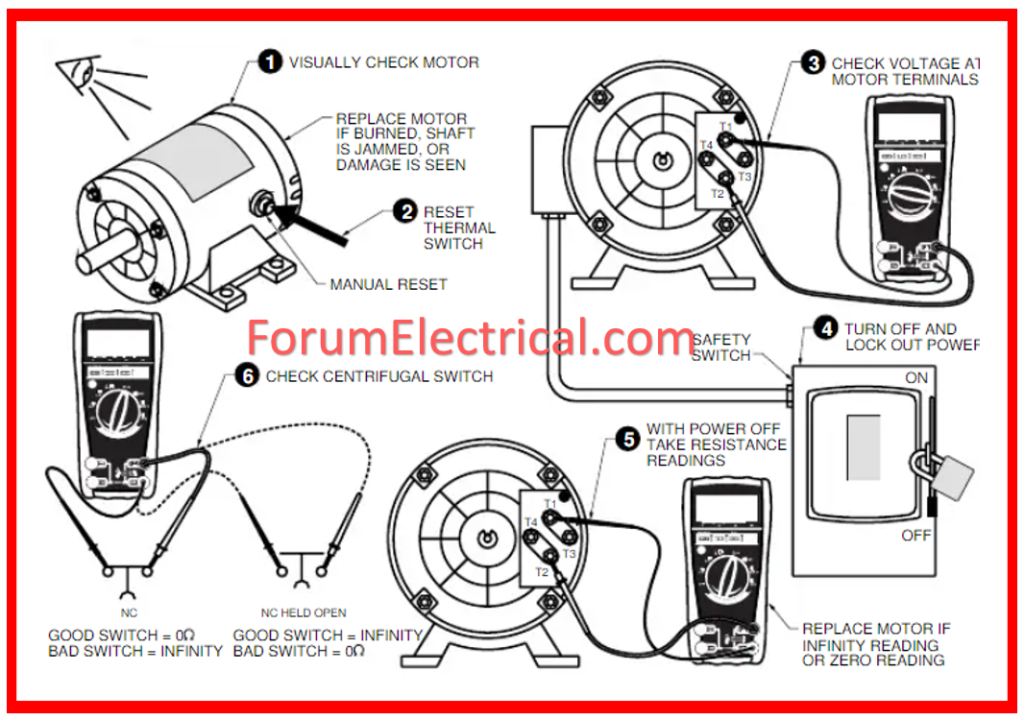
Physical Inspection of the Motor
A thorough physical evaluation of the motor is required before starting the testing process.
For the physical inspection, look for the following symptoms that indicate if the motor needs to be repaired or replaced.
- Inspect for any signs of wear to the casing.
- Check for weak connections.
- Inspect the alignment of the shaft.
- Check for excessive vibrations.
- Listen for odd noises.
- Check the temperature in the housing.
- Examine for excessive heat arising from the motor.
- Check the voltage and amps against the nameplate rating.
- If the motor includes brushes, check for wear.
- If the motor possesses capacitors, inspect them for leakage or damage.
Types of Single Phase Motor Test
Single phase motor tests typically reveal three different types of problems as listed below.
- Winding insulation resistance tests
- Winding coil open test
- Short-circuit test
Insulation Resistance Test
Insulation resistance tests are conducted on both running & starting windings.
Following this, we can determine whether or not the insulation on both windings is enough.
This test can be performed in two ways: with a testing lamp or with a multimeter.

Open Circuit Test
The open circuit test is performed or executed on windings that are both running and starting.
After this, we will be able to determine if both windings are open or closed.
There are two different sorts of tests that can be performed for this test:
- Testing lamp methods and
- Multimeter methods.
Short Circuit Test
The short circuit test is performed or implemented on windings that are both running and starting.
Following this, we will be able to determine whether one of the windings is short or whether they are not body (or) each other.
There are two different sorts of tests that can be performed for this test:
- Testing lamp methods and
- Multimeter methods.
Earth Continuity and Resistivity Tests
This testing procedure is utilized to assess the reliability of an electrical circuit.
It is used to ensure that there are no breaks in the circuit & that electricity flows smoothly through it.
This test is essential for making sure the safety of electrical equipment & avoiding potential risks.
The test is carried out by measuring the resistance across two circuit locations.
If the measured resistance is excessively high, it indicates a circuit failure.
If the measured resistance is too low, it suggests a short circuit.
Power Supply Test
The power supply test determines whether the power supply’s voltage and amperage are within the manufacturer’s specifications.
This test is critical to preventing damage to the motor (or) other electrical components.
The voltage must be within 10% of its nameplate rating. If not, there is an issue with the power source or the motor.
Make sure all of the cables are tight & secure.
Loose connections could lead the motor to overheat, creating a fire danger.
If the single-phase electric motor has capacitors, you should also examine them.
Capacitors are used to store electricity & help motors start and run.
If they are damaged, the motor may stop working properly.
Motor Winding Resistance Test
The winding resistance test is used to assess the durability of an electric motor’s winding.
It is used to ensure that there are no breaks in the winding & that current flows easily through it.
The winding resistance is determined using a multimeter.
If the multimeter reads infinite, it signifies there is an open circuit in winding that needs to be corrected.
- If it displays 0, it indicates a short circuit in winding.
- If it is between 0 & infinity, it indicates that the winding is in good condition, with no breaks (or) short circuits.
A low resistance ohmmeter can be used to obtain a more precise reading.
This type of ohmmeter is significantly more accurate and can detect extremely minor resistance changes.
Full Load Amplifier (FLA) Test
FLA is the most frequent method for testing a single-phase electric motor.
The test consists of providing a full load to the motor & measuring the resulting amps supplied.
This gives a great perspective of the motor’s general health and capacity to bear loads.
There are two major types of full load amp (FLA) tests:
- No-Load Test
- Load Test
No-Load Test
This is the most basic form of the test, which only requires calculating the amps drawn with no load applied.
This can be accomplished by removing the motor from all load devices & connecting the multimeter in line to determine the current draw.
Load Test
This test is accurate because it measures amps drawn at load conditions.
To accomplish this, connect the motor to its typical load devices and run it at full load for a period of time.
The resulting amp draw can be recorded.
Types of Testing Methods
When the motor did not function properly, we were required to check for fault detection.
There are various types of testing methods.
As will be seen in the following list, there are three different types of motor testing methodologies accessible.
- Testing lamp test methods.
- Multimeter test methods.
- Megger test methods.
Testing Lamp Test Methods
A test lamp is a circuit for an instrument. It has a series connection to malfunctioning equipment.

Insulation Resistance Test
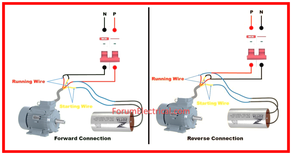
Two windings make up a single phase motor: one is for running and the other for starting.
One winding is linked in series with a test bulb to perform an insulation resistance test.
Phase is connected to the first rest wire point of the test light, and neutral is connected to the second winding rest point.
The insulation or winding is normal if the test lamp glows when it is dimly lit.
The winding insulation has burned off or the winding is not normal if the test lamp glows brightly.
It indicates the need for rewinding.
The same procedure can be used to verify the other second winding.
Open Circuit Test
One winding is connected in series with the test lamp for an open circuit test, while the other winding is connected at one point, and the test lamp’s point is connected to the supply.
The winding is normal if the testing lamp is shining. If there is no light coming from the lamp, the winding may be broken.
The second winding can be wound using the same procedure.
Short Circuit Test
The body and windings are tested for short circuits as a short condition.
A single winding is linked in series with a test lamp, while the other winding’s rest point is connected to the body and the neutral is connected to the body.
The body of the winding is short if the light is blazing. Other windings can be used in the same way.
Multimeter Test Methods
A multimeter is a measuring tool used to examine the values of equipment parameters such as resistance, continuity, voltage, and so on.

Insulation Resistance Test
For the insulation test, the multimeter knob is set to resistance mode, and the meter leads are attached to the windings at both ends.
Check the displayed resistance value.
Follow the same steps for the second winding. Compare the resistance values of both windings.
Open Circuit Test
The open circuit test is also known as a continuity test.
Set the multimeter knob to continuity.
Attach the lead to the windings at both ends. If the continuous sound is heard, then the winding is normal.
If there is no sound, then the winding is open. Repeat the technique for the other windings.
Short Circuit Test
A short circuit test is performed between the body and the windings themselves.
Set the multimeter knob to continuity mode.
The first lead of the meter is linked to the motor body, and the 2nd lead is connected to both windings one at a time.
If the sound is arriving, winding is done with the body.
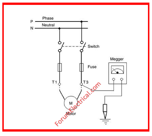
Megger Test Methods
Megger is a high voltage (HV) resistance tester that is used with large cables, HT lines, and motors.
Insulation Resistance Test
Megger is utilized for large single-phase motors.
If it is analog, adjust the handle. If the displayed value is infinity, then winding insulation is normal.
If the value is 0, the winding insulation will not be typical.
Open Circuit Test
Connect the megger testing leads to the winding termination points.
Short Circuit Test
Connect the megger testing leads to the motor’s windings and body locations.
How do you test Single-Phase Motor Windings?
To test the single-phase motor windings, follow the below 8 step procedure:
Step-1. Disconnect Power: To avoid accidents, unplug the power to the motor.
Step-2. Visual Inspection: Check the motor for any evidence of damage or wear.
Step-3. Resistance Testing: Using a multimeter, measure the resistance between the motor windings. Compare the readings to the manufacturer’s specs to confirm they are within the allowed range.
Step-4. Continuity Testing: Check the connection between the windings and the motor housing. There must be no continuity, suggesting proper insulation.
Step-5. Insulation Resistance Testing: Check the insulation resistance to ensure there are no shorts or flaws in the winding insulation.
Step-6. Rotor Check: Ensure that the rotor spins freely & is not hindered.
Step-7. Consult Manual: The motor’s manual contains particular testing protocols and acceptable values.
Step-8. Professional Assistance: If you are unclear or the readings are abnormal, contact a certified technician for further diagnostic and repair.
How many Ohms should a motor read to ground?
In general, it’s desirable for the motor to have the lowest possible impedance to ground.
However, several factors can influence this value, including the type of motor, its size, and the application.
In general, lower impedance measurements suggest a higher-performing motor.
What is a good ohm reading for a motor?
In terms of motors, the lower the ohms reading, its more efficient.
This is because lower resistance allows the motor to turn on and off more readily, resulting in less energy wasted as heat.
For most applications, a measurement of less than 0.5 ohms is regarded optimal.
Relevant Codes & Standards
Single-phase motors are often tested with the following standards:
- IEEE 112: This standard specifies the processes for testing electric motors, particularly single-phase motors. It addresses a variety of issues including efficiency, temperature rise, vibration, & noise.
- IEC 60034: Part 2-1 of the International Electro-technical Commission standard describes how to test the performance of spinning electrical devices, such as single-phase motors.
- NEMA MG1: The National Electrical Manufacturers Association published this standard, which covers the performance of motors and generators, including single-phase motors. It offers rules for testing techniques and performance metrics.
- UL 1004: Underwriters Laboratories (UL Standard 1004 specifies safety criteria for electric motors, particularly single-phase motors. It outlines test techniques to guarantee that safety criteria are fulfilled.
These standards establish extensive rules for testing single-phase motors, including efficiency, power output, temperature rise, insulation resistance & safety requirements.