
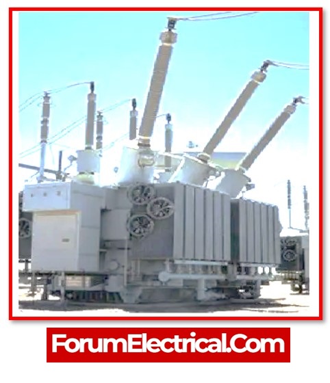
What is a Transformer?
A static device that operates according to the principles of electromagnetic induction is referred to as a transformer. Alternating current in the primary winding of the transformer causes a variable electromagnetic field to be formed, which in turn generates electromagnetic fields in the secondary winding of the transformer. The magnitude of the electromagnetic field that is created by the turn’s ratio is directly proportional to that value.
- What is a Transformer?
- What are the 14 Essential Parts of the Transformer?
- 1). Core
- 2). Winding
- 3). Insulation
- 4). Tank
- 5). Terminals and bushings
- 6). Transformer Oil
- 7). Conservator Tank (or) Oil Conservator
- 8). Breather
- 9). Radiators and Fans
- 10). Explosion Vent
- 11). Tap Changers
- 12). Buchholz Relay
- 13). Temperature Gauge
- 14). Cooling Tubes
- Why are copper windings in transformers used?
Due to its characteristics that it is a static electrical device without any rotating components, its efficiency is very high (more than 95%).
- The transformer’s core,
- Theprimary, and
- Thesecondary windings
are its fundamental components.
In addition to these, a number of other parts of installed equipment, such as the cooling systems,
- The protection relay (Buchholz relay),
- The HT & LT terminals & bushings,
- The breather,
- The conservator,
- Thee oil tank,
- The explosion vent,
- The tap changer, etc.,
are also regarded as parts of the transformer.
Let’s describe each transformer part’s function.
What are the 14 Essential Parts of the Transformer?
Transformers are key electrical devices that use electromagnetic induction to transmit electrical energy between two (or) more circuits. They are made up of several important parts, each of which has a distinct purpose. Here are the many components of a transformer & their functions:
The different transformer parts are as follows:
1). Core
2). Winding
3). Insulation
4). Tank
5). Terminals and Bushings
6). Transformer Oil
7). Conservator Tank (or) Oil Conservator
8). Breather
9). Radiators and Fans
10). Explosion Vent
11). Tap Changers
12). Buchholz Relay
13). Temperature Gauge
14). Cooling Tubes
1). Core
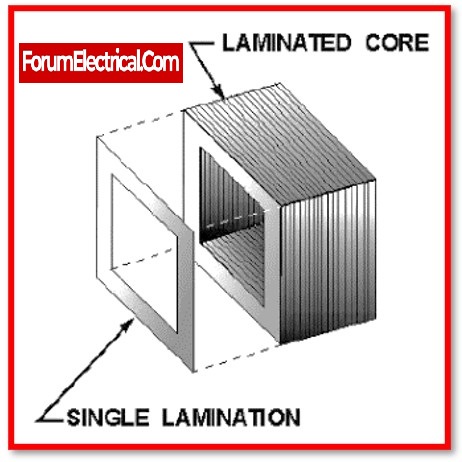
The primary & secondary windings are supported by the core, and it provides an electromagnetic flux transmit with low resistance. It is constructed by stacking thin insulating sheets between high-grade, grain-oriented steel sheets.
In order to minimise the effects of hysteresis and eddy currents, the proportion of carbon in the core steel is maintained below 0.1 percent. Eddy currents may be decreased by alloying it with silicon.
The primary & secondary winding of each phase are carried by each limb. The yokes magnetically connect the limbs together.
- Core type &
- Shell type
are the two distinct types of core structures.
The core surrounds the windings in a shell-type structure.
2). Winding
Primary and secondary winding sets are carried by the transformer for each phase. Numerous turns of copper (or) aluminium conductors compose these winding, which is isolated from the transformer core and one another. Transformer winding types and configurations are determined by factors including
- Current rating,
- Short circuit power,
- Temperature increase,
- Impedance, &
- Surge voltages.
The primary winding & secondary winding are divided into two sections:
- The primary winding is known as the HV – High Voltage winding, and
- The secondary winding is known as the LV – Low Voltage winding.
The LV winding is surrounded from the outside by the high-voltage winding conductors, which are thinner than low-voltage conductors. Close to the center is where the LV winding is located.
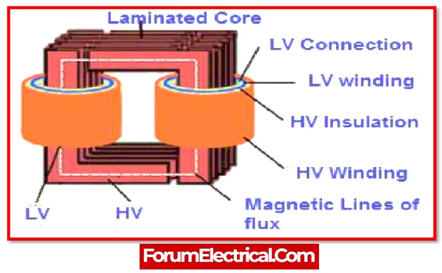
The winding is divided into a number of coils (only a few turns of a conductor) in shell-type transformers. In between the LV coils are the HV coils.
On the other end, there are four distinct types of windings in core-type transformers:
- Multi-layer windings,
- Helical windings,
- Disc windings, and
- Foil windings.
The number of turns and current carrying capacity affect the winding type selection.
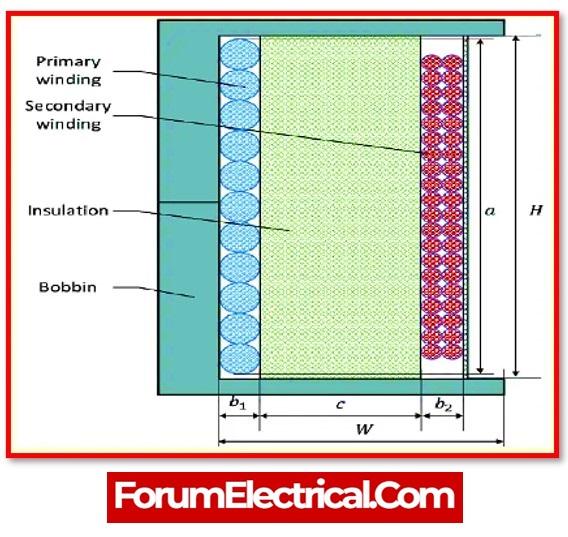
3). Insulation
The most essential part of transformers is insulation. Transformers are most likely to experience severe damage from insulation failures. There must be insulation
- Between the core and the windings,
- Between each and every turn of the winding, and
- Between every component that carries current and the tank.
- High dielectric strength,
- Superior mechanical qualities, and
- High temperature resistance
should all be featured in the insulators.
Transformer insulation is made of
- Synthetic materials,
- Paper,
- Cotton, and
- Other materials.
4). Tank
The main tank is a component of a transformer with two functions:
- Shields the windings and core from the outside (external) environment.
- Provides support for all additional transformer attachments as well as a container for oil.
Rolling steel plates are formed into vessels to create tank bodies. They are given cooling tubes and lifting hooks.
Aluminium sheets are also utilised in place of steel plates to minimise weight and stray losses. But aluminium tanks are more expensive than steel ones.
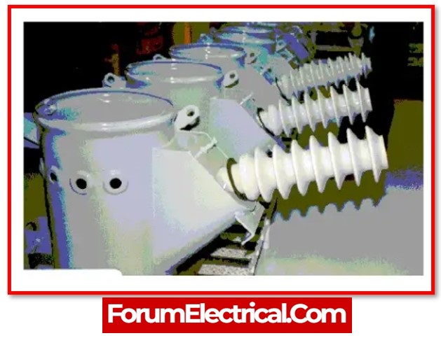
5). Terminals and bushings
Transformers include terminals for connecting incoming & outgoing wires. They are installed on the bushings & attached to the ends of the windings.
Between the terminals & the tank, bushings, which are insulators, provide a barrier. The tanks for the transformers are located above them. The wires connecting the terminals to the windings may pass through them safely. Porcelain (or) epoxy resins are used in their manufacture.
6). Transformer Oil
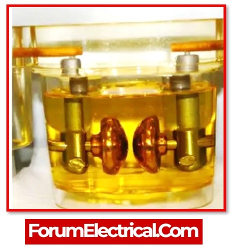
Transformer oil provides improved heat dissipation, fault detection capabilities, and additional insulation between the conducting elements of all oil-immersed transformers. Transformer oil is made of hydro-carbon mineral oil. It is made up of
- Olefins,
- Paraffin,
- Aromatics, and
- Naphthene’s.
Transformer oil has a density of 0.96 kg/cm3, a flashpoint of 310 °C, and relative permeability of 2.7.
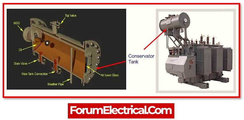
7). Conservator Tank (or) Oil Conservator
The oil conservator is positioned well above the tank & bushings and is relocated onto the top of the transformers. Some oil conservators often have a rubber bladder.
As the temperature rises and falls, the transformer oil expands & shrinks. The oil conservator has sufficient space to accommodate oil expansion. It has a pipe leading to the main tank.
A level indicator that displays the present level of oil contained inside the conservator has been filled into it.
8). Breather
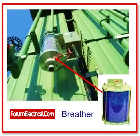
A breather is included in the structure of any oil-immersed transformer that also includes a conservator tank. It is essential that the oil be maintained in a dry and moisture-free environment. Because of changes in temperature, which cause the transformer oil to get expand and come into contact with one another, the conservator tank is subject to the entry and expel of air.This air should not contain any moisture. This can be achieved by means of ventilation.
The end of the air pipe has a breather connected to it in order that it may act as the entrance and exit to the conservatory at the same time. By extracting moisture from the air and giving air that is free of moisture to conservator, the silica gel that is contained in the breathers can maintain its stability.
9). Radiators and Fans
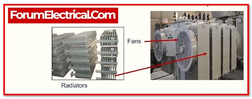
Heat is generated when power is lost in the transformer. Most dry transformers use natural air cooling. However, a number of cooling techniques are used when it applies to oil-immersed transformers.
Radiators and cooling fans are positioned on the transformer tank in accordance with the kVA rating, power losses, & degree of cooling needed.
The ambient transformer oil that absorbs the heat generated by the core and winding. This heat is emitted from the radiator.
Forced cooling is accomplished in larger transformers by radiator-mounted cooling fans.
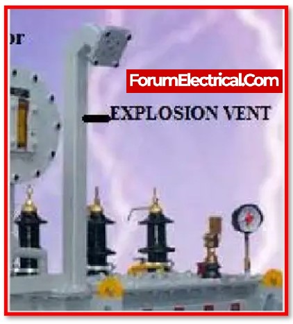
10). Explosion Vent
Inside a transformer, an explosion vent serves as an emergency outlet for air and oil fumes. It is a metallic pipe that extends close to the conservator tank and has a diaphragm at one end.
When there is an oil leak, the pressure within the tank might reach deadly heights. Under these conditions, the transformer’s diaphragm ruptures at the relatively low pressure, releasing internal forces into the environment.
11). Tap Changers
Transformers’ secondary voltage may be changed using tap changers. They are made for changing the transformer’s turn ratio as required.
- On-Load Tap Changers – On-load tap changers can function while the current is still flowing to the load and
- Off-Load Tap Changers –Off-load tap changers can only function when the transformer doesn’t supply any loads.
are the two different types of tap changers.
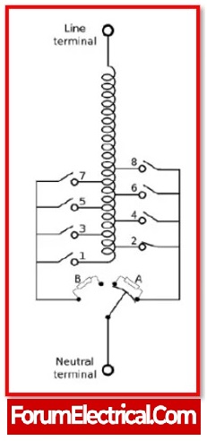
There are also automatic tap changers available.
12). Buchholz Relay
One of the most essential parts of the oil-immersed transformers rated above 500kVA is the Buchholz relay. A relay that is triggered by oil and gas is used to detect flaws (faults) in components that are submerged in oil.
Transformer oil short circuits generate sufficient heat for the oil to decompose into
- Methane,
- Carbon monoxide, and
- Hydrogen.
Through the connecting conduit, these gases migrate progressively towards the conservator tank.
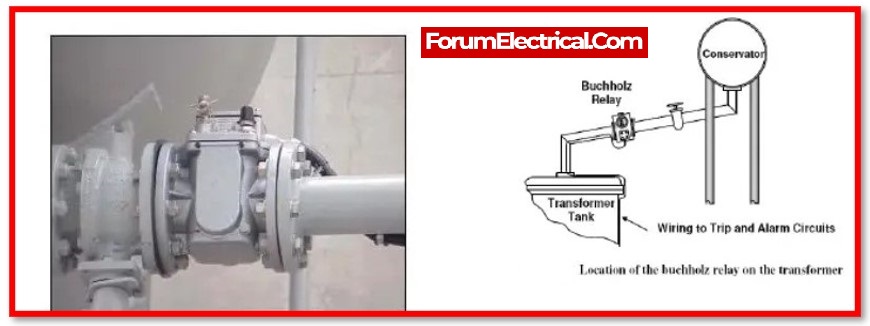
The trip and alarming circuits are activated when these gases are detected by the Buchholz relay, which is located on the pipe that connects the conservator tank & the main tank.
The trip circuit interruptions the current flow and opens the circuit breaker controlling the primary winding.
13). Temperature Gauge
A temperature gauge is a device used to check the temperature of the power transformer. To gauge the temperature of the transformer, it is positioned on top of the tank. This thermometer has a light or alarm that notifies as the temperature rises.
14). Cooling Tubes
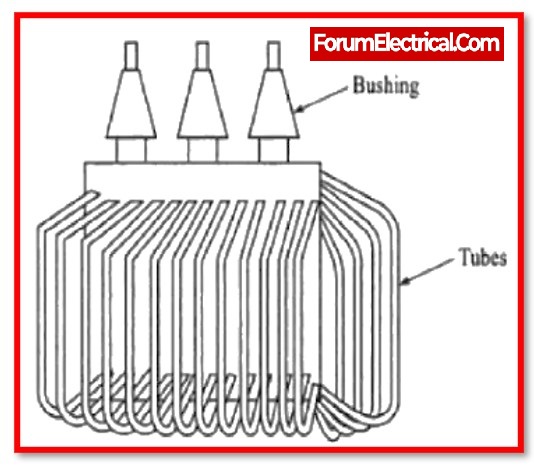
As its name implies, cooling tubes are used to cool the transformer oil. Inside the transformer, oil may flow freely or mechanically.
The heated oil rises to the top automatically during natural circulation as the oil temperature increases. While an everlasting pump is employed to forcefully circulate the oil between the hot & cold zones, the cold oil automatically flows.
Why are copper windings in transformers used?
Due to characteristics of copper, transformer & all other electrical machine windings are constructed from high-quality copper material.
- Due to its more effective conductivity relative to other materials, copper is an excellent conductor of electricity. Thus, the power losses in the windings are minimised.
- The increased ductility of copper is another notable characteristic. This indicates that it is simple to bend conductor into a tight wrapping around the transformer core, which reduces the quantity of copper and its volume and weight that must be used.
