Table of Contents
- Purpose
- Scope
- Personal Protective Equipment (PPE)
- Responsibility
- Work Activity & Descriptions
- Test Procedure
- Step-1: Visual & Mechanical Inspection
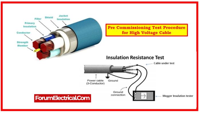
- Step-2: Insulation Resistance (IR) Test for EHV Cables
- Step-3: IR between Phase to Phase
- Step-4: IR between Phase to Earth
- Step-5: High Voltage (Hi-Pot) Test: HV Cable
- Control Measures
- Final Inspections & Area Restoration after Work Completion
- Communication & Sign-off Register
Purpose
This method statement is designed to carry out numerous pre-commissioning tests for switchgears in a systematic manner to assure the healthiness & performance of the HV cable.
Scope
This procedure covers the pre-commissioning test for HV cables, including
- High Voltage (Hi-Pot) test,
- Insulation Resistance test.
Personal Protective Equipment (PPE)
- Safety Helmet
- PPE Kit
- Hand Gloves
- Safety Shoes
- Safety Glass
Responsibility
Unit Heads/Regional Managers
Unit Heads/Regional Managers are responsible for health & safety management,
- Including planning and scheduling activities,
- Identifying and minimizing hazards,
- Adhering to legal and statutory requirements,
- Assisting the safety team with training and audits, and
- Ensuring compliance with safety rules and regulations.
Site Engineers
Site engineers are responsible for all areas of on-site health and safety and report to the Unit head / Regional Manager.
Their responsibilities include:
- Report any health and safety issues at work sites to the regional manager, unit head, or safety team.
- Coordinate with clients to obtain and return work permits.
- Communicate work content and hazards to working groups through meetings before each day’s start.
- Implement proactive measures to reduce accidents.
- Report incidents in detail.
- Use “Stop Work” in case of major safety violations.
Safety Engineers
Safety managers and regional safety engineers are in charge of giving health & safety advice & direction to their unit head, regional manager, and site engineers.
Their responsibilities include:
- Communicate all safety rules, regulations, and procedures to site engineers, regional managers, and unit heads.
- Follow up on audit non-conformances and assist regional managers/unit heads in taking remedial and preventive measures. Report and investigate any occurrences or near misses to high management.
- Create awareness among site engineers and regional managers, and plan a regular training program.
- Conduct daily toolbox discussion sessions to ensure workers are knowledgeable of workplace hazards.
- Ensure suitable PPE and safety equipment are available and used on-site.
- Report any problems affecting the health & safety at the work site to the unit head/regional management.
- Ensure that fundamental first aid facilities are provided on site.
- Ensure no harmful acts are undertaken on any site.
- Eliminating harmful conditions on-site promptly.
- Issuing safety challans for any violations.
Work Activity & Descriptions
Pre-Testing Checks
- Check the operating status of the ELCB (30 mA).
- Inspect power cable insulation for equipment.
- Ensure suitable earthing and rubber matting are accessible at the worksite.
- Use calibrated testing equipment and provide engineers with calibration results.
- Check the technician’s insulation hand tools.
- Check the test leads for insulation damage.
- Make sure proper PPE is provided at the site.
- Human supervision is required at both ends of the cable.
Resources: Tools and Equipment Required
For High Voltage Testing (Hi-pot test)
- High Voltage Test Kit
- Test Leads
- Insulation Tester (500 and 5000 V)
- Clamp meter and Insulated Hand Tools.
For Insulation Resistance Measurement Test (IR Test)
- Clamp meter
- Test Leads.
- Insulation tester (500-5000 V)
- Insulated hand tools

Test Procedure
Step-1: Visual & Mechanical Inspection
- Compare the cable data to the designs and requirements.
- Check exposed parts of cables for the physical damage.
- Inspect compression-applied connections for proper cable alignment and indentation.
- Inspect the shield grounding, cable supports, and terminations.
- Ensure that visible cable bends meet (or) exceed the ICEA and manufacturer’s minimum published bending radius.
- Inspect the fireproofing in the common cable places.
- If cables are terminated via window-type current transformers, inspect to ensure that neutral & ground conductors are correctly arranged and shields are correctly terminated for the operation of protective devices.
- Inspect for proper identification and organization.
- Check the cable jacket & insulation condition.
Step-2: Insulation Resistance (IR) Test for EHV Cables
- Obtain a work permission from the client.
- Ensure there is no energy in high voltage (HV) cable.
Step-3: IR between Phase to Phase
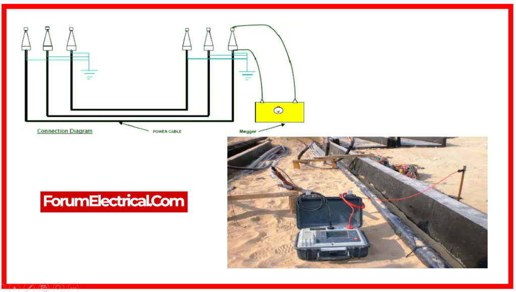
- Connect the first conductor for measuring cross insulation to the megger’s line terminal.
- Connect the remaining conductor to the earth.
- Connect the sheat to the earth terminal of the megger.
- Leave the conductor at the other end free.
- Turn on the megger and press the test button.
- Discharge the potential with a separate earth rod.
- Turn OFF the megger.
- Repeat for the other conductors.
Step-4: IR between Phase to Earth
- Attach the conductor to the megger’s line terminal.
- Attach the guard to the last remaining conductor.
- Loop the armor and shielded conductor to the soil at the closest place and in the megger.
- Repeat the previous steps for the additional conductors.
- Leave the other end free.
- Turn the megger ON & press the test button to record the reading.
- Discharge the potential using a separate earth rod.
- Turn the megger OFF.
Step-5: High Voltage (Hi-Pot) Test: HV Cable
- Obtain the client’s work permit.
- Ensure the bus bar terminal has no voltage and is earthed.
- During high voltage testing, earth all equipment associated to cable installation, including switches, instrument transformers, and busbars, and maintain clearance from other equipment and framework to minimize flashovers.
- Attach the Hi-Pot kit with the ELCB 30mA.
- Connect the test lead to the conductor and cable armor.
- Connect the other conductors (other phase) to the ground. Then, turn on the test kit, apply voltage to the cable, and take the reading. Finally, use a discharge rod to discharge the cable potential.
- Connect the clamp meter to the discharge rod, touching the cable points, to ensure zero voltage.
- Perform the preceding methods to measure the other phases.
Control Measures
- Testing engineers provide OCP for IR and Hi-Pot tests for HV cables.
- Make sure PTW system in setup for the specific bay.
- Ensure equipment supply is dead.
- Prevent unauthorized access to the testing area.
- Barricade the area with warning tape.
- Conduct job-specific toolbox meetings and supervise the area.
- Use calibrated equipment and insulated hand tools.
- Avoid power cable joints and supply via ELCB.
- Avoid working alone.
- Wear arc flash suits and avoid high-potential tests.
- Use proper insulated hand gloves.
Final Inspections & Area Restoration after Work Completion
- Remove the barricading tapes and disconnect the temporary supply.
- Make sure that the space is free of any loose materials or tools.
- As you depart, make sure the area is neat and clean.
Communication & Sign-off Register
Communicate to all staff in meetings, and ensure that all personnel sign it.


