 and their advantages, disadvantages and applications.)

- What is Core Balance Current Transformer?
- Working principle of a Core Balance Current Transformer (CBCT)
- Selection of Core Balance Current Transformer (CBCT)
- Characteristics of Core Balance Current Transformer (CBCT)
- Advantages of Core Balance Current Transformer (CBCT)
- Disadvantages of Core Balance Current Transformer (CBCT)
- Applications of Core Balance Current Transformer (CBCT)
What is Core Balance Current Transformer?
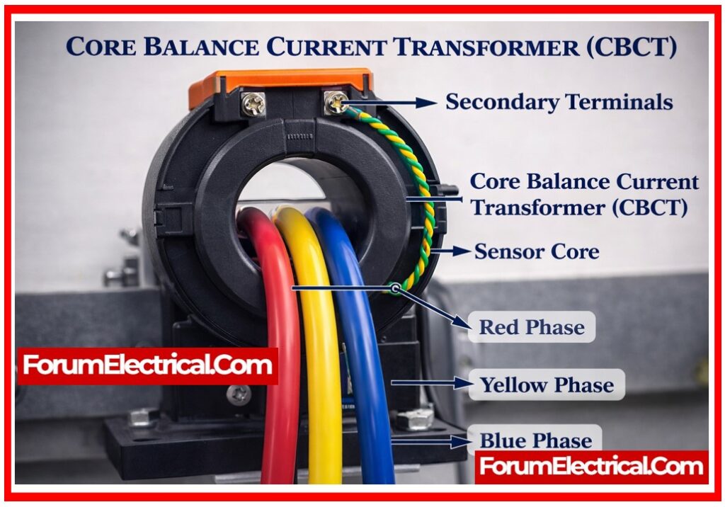
A magnetic coil is wound on a core of the ring type to create the particularly built current transformer known as a core balance current transformer. This coil serves as a backup coil. A primary winding is often created by passing two (or) more live conductors through a ring-shaped core.
For the electrical protection system, Core Balance Current Transformers serve a very important purpose. It functions essentially as a current sensor. It can detect the imbalance current and output when it occurs in a circuit as a result of an
- Earth fault,
- Earth leakage, or
- Ground fault.
It serves as a protective system’s fundamental device. When a fault occurs, it transmits the signal to the protecting device to break the circuit.
It is also called as a Zero Sequence Current Transformer (ZCT).
A circular ring is formed by the secondary coil with the most turns, through which three single-core cables (or) a single three-core wire of a three-phase system flow. As previously mentioned, the primary of the CBCT is formed by this three-phase wire system.
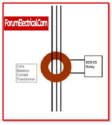
According to the diagram, the CBCT is a current transformer via which all three phases are made flow.
The three phase currents’ magnetic fluxes cancel each other out as a result.
Since the net resultant flux is zero, the transformer‘s secondary does not experience any current. Since all three phases are healthy, the secondary current of the CBCT is zero. A current is induced in the secondary when an earth fault emerges in one of the phases because the zero-sequence fault current that flows is not neutralized by the flux of the other two phases. To create the tripping signal, an earth fault relay that is coupled to the CBCT might be employed.
Working principle of a Core Balance Current Transformer (CBCT)
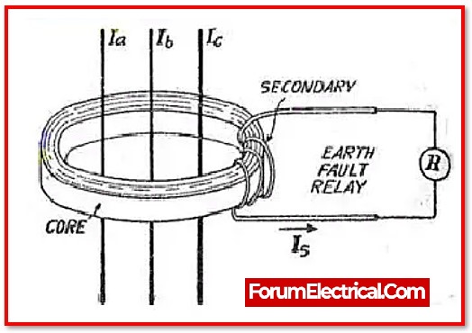
An example of a CBCT is shown in the image above. As indicated, the 3 phase currents are Ia, Ib, & Ic. The secondary is being linked to the relay, and these three-phase wires comprise the primary.
The zero-sequence current balance is the basic principle of how current transformers operate. It is also known as a Zero Sequence Current Transformer (ZCT) for this reason.
In a three-phase system, a zero-sequence voltage or current occurs when all the 3 phases have voltages or currents of equal magnitude and symmetry.
When all of the parameters in a zero-sequence system add up to zero algebraically, the system is said to be balanced. It is quite similar to Kirchhoff’s current law that states the total current flowing through a node equals zero.
The algebraic sum of the phase current hence equals 0 in normal operation.
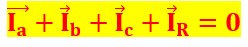
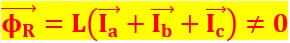
Since there is no fault condition, the consequent residual current is also said to be equal to zero, as is the zero-sequence current. As it is directly proportional to the corresponding current, the residual current’s consequent magnetic field flux is similarly zero.


Where ,
Φ – generated magnetic field flux
IR – Resultant current
L – Inductance coil
As a result, the current and magnetic field flux are directly proportional. The magnetic field flux created from the primary which connects with the secondary of the CBCT is zero since the residual current is zero, and as a result, no current flows along the secondary of the CBCT.
The three-phase system no longer maintains the balanced condition as it once maintained after a defect like a line-to-earth fault (or) a line leakage fault, subsequently the sum of the phase currents is not equal to zero. As a result, the system generates a finite value zero sequence current, which results in the generation of a magnetic field.
Let Ia, Ib, and Ic, respectively, be the phase currents, and let Φa, Φb, and Φc be the resulting magnetic fields.
Therefore,
A low-value current flows through the secondary coil of the current transformer when this magnetic field connects with the secondary of the CBCT. A relay receives this secondary coil current, activates, and transmits a trip signal to circuit breaker. Thusly engaged, the circuit breaker protects the entire power system by cutting off the supply to fault zone.
The magnitude and phase of the zero sequence currents are identical. Consequently, the current in zero sequence that result is
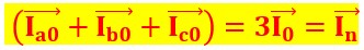
Where,
In-Neutral current
which is not zero when there is a fault or when the system is unbalanced. The magnetic field necessary for the CBCT to function is generated by this current.

The system is balanced in a normal condition, hence the total of the zero sequence currents is zero. As a result, no subsequent magnetic field flux is produced.
A Core Balance Current Transformer, also known as a Zero Sequence Current Transformer, operates on this basis.


Selection of Core Balance Current Transformer (CBCT)
The proper zero sequence CT (or) CBCT is chosen depending on the parameters listed below:
- The nominal CT ratio must be enough to ensure that even with the smallest ground fault, the current is sufficient to operate the earth fault relay.
- Primary (main) ground leakage current is kept to a minimum.
- Relay operating voltage requires a minimum excitation current.
- Voltage at the exact point
- CT dimensions & internal diameter (internal diameter varies depending on cable size)
Characteristics of Core Balance Current Transformer (CBCT)
1). Core Design
The conductor is surrounded by a toroidal core in CBCT designs. The CBCT can measure the current without being intrusive because to its fundamental design.
2). Accuracy
CBCTs have extremely low measuring errors-generally less than 1%. Over a large variety of currents and frequencies, this accuracy is maintained.
3). Installation
CBCTs may be installed quickly and without interrupting the power source. The CBCT is simply clamped around the conductor to install them.
4). Safety
CBCTs are secure to set up and use because they don’t need to be physically connected to the conductor. Additionally, they don’t add any extra electrical noise to the system.
5). Output Signal
CBCT’s typically generate an output signal that is directly proportional to the conductor current. There are several uses for this signal, including monitoring, controlling, and protecting.
6). Size
CBCT’s can be found in a variety of sizes, from compact devices for domestic and commercial use to bigger equipment for industrial use.
7). Cost
Because they don’t need a solid core (or) secondary winding, CBCTs are typically less expensive than conventional current transformers (CT’s). They are therefore a desirable solution for numerous applications.
In general, CBCT’s are an efficient and dependable method for determining AC currents in a range of applications.
Advantages of Core Balance Current Transformer (CBCT)
- The primary advantage of adopting CBCT as an earth fault prevention system is that, instead of using three CT cores as in a typical system, only one CT core is utilized in this protection method.
- As a result, the magnetic flux needed to produce the secondary current is lowered to one-third (1/3), which is the most advantages as the protection system’s total sensitivity increases.
Disadvantages of Core Balance Current Transformer (CBCT)
- The conductor must be entirely enclosed within the magnetic core of the transformer, which is a CBCT’s primarily disadvantage. As a result, it cannot be used with large conductors since the transformer could be too big and difficult to operate.
- Additionally, CBCTs are less effective for applications involving several conductors since they are able to measure the current in the single conductor at a time.
- CBCT’s’ inability to measure direct current(DC) since they only operate with alternating current(AC) is another disadvantage.
Applications of Core Balance Current Transformer (CBCT)
1. CBCT is found in power control panels.
2. CBCT circuits are employed in motor protection circuits.
3. CBCT is used to protect heavy or large electrical machinery.
4. A leakage current measurement system employs CBCT.
5. CBCT is employed in the installation of high range electrical power systems.