
Solar generation losses are the unseen adversarial of plant performance.
- Solar Generation Losses
- Traditional Solar Generation Losses
- 1). Shading Losses
- 2). Soiling Losses
- 3). Temperature Losses
- 4). Conversion Losses
- 5). Degradation Losses
- 6). Weather & Irradiance Variability
- 7). Reflection and Angle Losses
- 8). Degradation due to LID & PID
- 9). Battery Storage and Charge Controller Losses (Hybrid Systems)
- Modern losses in Utility-Scale Plants
- 1). Clipping Losses
- 2). Communication Losses
- 3). Inverter Wake-up & Sleep Delays
- 4). Grid Outages (or) Frequency Drift Losses
- 5). Tracker Stow Losses
- 6). Thermal Shutdown and Derating
- 7). AC Collection System Losses
- 8). Sensor Calibration Errors
- 9). Inverter Configuration (or) Firmware Limits
- Conclusion
Solar Generation Losses
- Plant Performance Ratio (PR),
- Energy Yield, &
- Financial Returns.
Managing multi-megawatt (MW) solar resources, it is clear that understanding both classic and new loss types is necessary for effective operation and asset longevity.
Top Solar Generation Losses You Should Know: Traditional and Modern Losses
Here’s a thorough list that includes both traditional and developing loss categories in utility-scale PV systems:
Traditional Solar Generation Losses
These are well-known and are frequently handled in standard design, operation and maintenance, and performance monitoring techniques.
1). Shading Losses
2). Soiling Losses
3). Temperature Losses
4). Conversion Losses
5). Degradation Losses
6). Weather & Irradiance Variability
7). Reflection and Angle Losses
8). Degradation due to LID & PID
9). Battery Storage and Charge Controller Losses (Hybrid Systems)
1). Shading Losses
Even partial shadowing of a solar module can have a significant impact on output due to the series connectivity of cells.
Shadows cast by trees, neighboring buildings, poles, antennas, and even adjacent panel rows in the early morning or late evening might cause an imbalance in current generation.
Impact: Depending on the shading pattern, time & module string setup.
Solution: Optimize site architecture, use bypass diodes, and implement string-level MPPT or MLPEs.
2). Soiling Losses
Dust, bird droppings, sand and industrial pollution that settle on the module surface impede light transmission.
Soiling in dry and semi-arid zones can result in 5% to 10% (or) more energy loss if panels aren’t cleaned on a regular basis.
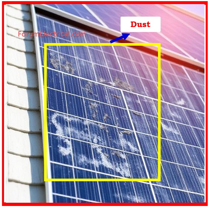
Impact: Greater during the dry season and in dusty places.
Solution: Site-specific cleaning schedules, soiling sensors, & predictive cleaning intervals.
3). Temperature Losses
Solar panels are less efficient at higher temperatures.
The efficiency of the crystalline silicon modules decreases by ~0.4 to 0.5% per °C over the STC (Standard Test Conditions).
Impact: In hot areas, losses might range from 8 to 15%.
Solution: Use high-efficiency modules, improve module ventilation, & choose locations with optimal temperature-wind profiles.
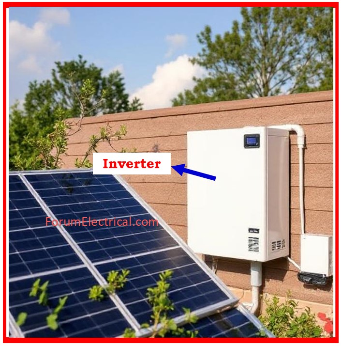
4). Conversion Losses
Inverters transform DC power from the panels into the usable AC power.
This DC-AC conversion is never completely efficient, & conversion losses commonly vary between 2% and 3.5%.
Impact: Affected by inverter quality, load, and temperature.
Solution: Choose high-efficiency inverters, operate around optimal load points, and provide proper ventilation.
5). Degradation Losses
Solar modules degrade with time, resulting in lower energy output.
Typical deterioration rates range between 0.5% and 1% per year, with higher rates in areas with significant temperature changes, humidity, (or) UV exposure.
Impact: Long-term performance decline.
Solution: Select Tier 1 modules with the low degradation rates & conduct periodic IV curve testing to monitor performance.
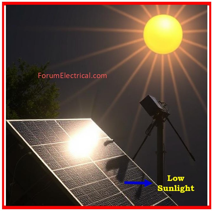
6). Weather & Irradiance Variability
sun generation is directly proportional to sun irradiation. ‘
Cloud cover, fog, haze and seasonal fluctuations all have an impact on the amount of solar energy received.
Impact: Variations in daily and seasonal yields.
Solution: Analyze historical weather data to design plants, use accurate irradiance sensors (GHI/DHI) & forecasting tools.
7). Reflection and Angle Losses
Improper tilt angles & orientation (azimuth) limit the amount of sunlight absorbed by panels.
A fixed array which is not optimized for its geographic location may experience a 1-3% energy loss.
Impact: If not rectified, this will have an impact on year-round yield.
Solution: Tilt and azimuth are optimized based on location (or) by using single- or dual-axis tracking devices.
8). Degradation due to LID & PID
Degradation caused by LID and PID LID (Light-Induced Degradation) occurs in the initial hours or days when solar panels are exposed to the sunlight, particularly in mono-PERC panels.
PID (Potential-Induced Degradation): High system voltage & poor insulation cause leakage currents across the solar cell & frame.
Impact: In worst-case coditions, output can be reduced by 5-30%.
Solution: Utilize PID-resistant modules, adequate grounding, and monitoring to discover issues early on.
9). Battery Storage and Charge Controller Losses (Hybrid Systems)
Energy loss in hybrid or off-grid systems occurs when battery charging, discharging, & conversion, which normally ranges between 10-15% depending on battery type & charger efficiency.
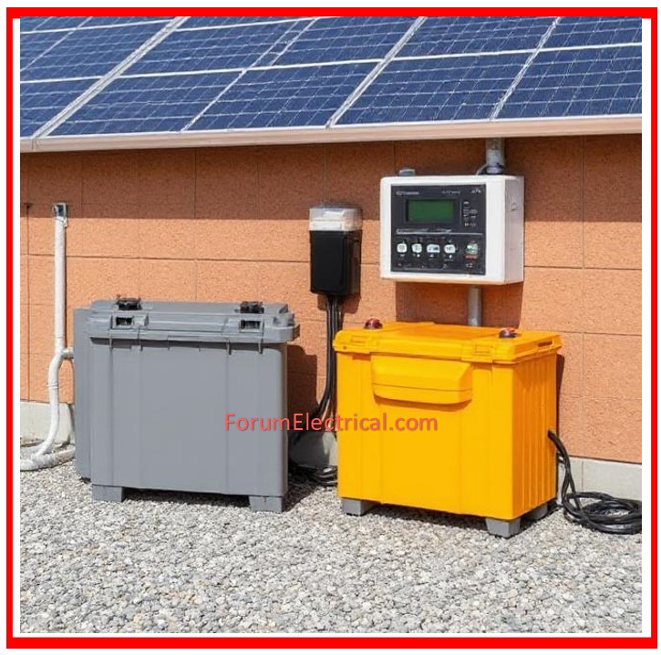
Impact: Essential in the energy storage-dependent systems.
Solution: Use high-efficiency MPPT charge controllers & lithium-based storage devices for improved round-trip efficiency.
Modern losses in Utility-Scale Plants
These losses are emerging (or) becoming more prevalent as a result of increased digital integration and growing technologies.
1). Clipping Losses
2). Communication Losses
3). Inverter Wake-up & Sleep Delays
4). Grid Outages (or) Frequency Drift Losses
5). Tracker Stow Losses
6). Thermal Shutdown and Derating
7). AC Collection System Losses
8). Sensor Calibration Errors
9). Inverter Configuration (or) Firmware Limits
1). Clipping Losses
This occurs if the DC input power surpasses the inverter’s rated AC output, particularly during peak sunlight hours.
The inverter limits the output, and any extra DC power is lost.
Impact: Common in systems with a DC:AC ratio of more than 1.2.
Solution: When designing an inverter, strike a balance between DC oversizing and available capacity.
2). Communication Losses
Communication breakdowns between SCBs (String Combiner Boxes), weather stations & inverters can delay problem identification and diminish plant visibility.
Impact: The impact is that faults remain unresolved for extended periods of time, diminishing uptime.
Solution: Reliable SCADA, redundant communication networks, & proactive O&M teams.
3). Inverter Wake-up & Sleep Delays
Inverters need a minimum voltage/current threshold to operate.
Late morning (or) early evening sleep can lead to generation loss, particularly during periods of low irradiation.
Impact: Reduced yield between dawn and sunset hours.
Solution: Utilize inverters with the low start-up thresholds & reconsider inverter placement for best results.
4). Grid Outages (or) Frequency Drift Losses
Inverters disconnect whenever grid parameters such as voltage, frequency, and phase angle exceed safe limitations.
Impact: Energy loss even when the sun is there.
Solution: Use grid-forming inverters, adjust frequency ride-through settings, & monitor grid functioning.
5). Tracker Stow Losses
Tracking systems adjust panels to face the sun radiation optimally.
However, in strong wind or storm circumstances, they will relocate to a stow position (horizontal/neutral) for the safety, resulting in a temporary loss of generation.
Impact: Yield loss is weather-dependent.
Solution: Use smart stowing algorithms & strong structural designs to reduce downtime.
6). Thermal Shutdown and Derating
When internal temperatures rise above a certain threshold, inverters (or) transformers may lower power or shut down.
Impact: Loss of generation over peak sunlight hours in hot areas.
Solution: Provide adequate ventilation, air cooling (in inverter rooms), or select equipment with the higher thermal limitations.
7). AC Collection System Losses
Losses occur in AC cabling, couplings, connectors, & transformer windings, particularly in big operations with lengthy cable lengths.
Impact: Often missed, but quantifiable in PR analysis.
Solution: Use proper cable sizing, jointing techniques & conduct frequent thermographic inspections.
8). Sensor Calibration Errors
Faulty (or) uncalibrated irradiance, temperature and wind sensors can lead to inaccurate PR (Performance Ratio) computations and impact performance assessments.
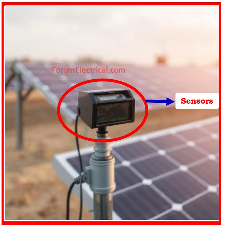
Impact: Skewed data influences decision-making.
Solution: Regular calibration & cross-validation with the portable devices.
9). Inverter Configuration (or) Firmware Limits
Some inverters contain factory-installed output caps, outdated software, or unused features that might reduce output.
Impact: Despite favorable conditions, underperformance occurred.
Solution: Perform regular firmware upgrades, tune inverter parameters, and examine OEM setup settings.
Conclusion
Solar generation losses are complex and dynamic, spanning from environmental factors to equipment behavior & digital communication difficulties.
By detecting and reducing these losses, both traditional and new, plant operators may greatly improve the production, PR, & ROI of the utility-scale solar assets.
To maximize performance:
- Monitor systems in the real time.
- Analyze the loss components regularly.
- Implement predictive maintenance.
- Review the design and commissioning data.


