
- How do solar cells work?
- Symbolic Representation of Solar Cell
- Construction of the solar cells
- Working Principle of the Solar Cell
- VI Characteristics of the Solar Cell
- Parameters of a Solar Array
- Materials in Solar Cells
- Material Selection Criteria for Solar Cells
- Advantages of the Solar Cells
- Disadvantages of the Solar Cells
- Applications of the Solar Cells
How do solar cells work?
A solar cell is an electrical device that, through the use of the photovoltaic effect, is able to convert the light energy that it receives into electrical energy. Photovoltaic cells & PV cells are different terms for solar cells.In its most basic form, a solar cell is a p-n junction diode. The term “photoelectric cell” refers to a device whose electrical properties, such as current, voltage, or resistance, change when the device is exposed to light. Solar cells are a kind of photoelectric cell.
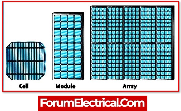
Individual photovoltaic cells may be assembled into modules, which are more frequently referred to as solar panels. The typical silicon solar cell with a single junction is capable of producing a maximum open circuit voltage that ranges anywhere between 0.5 and 0.6 volts. These solar cells are actually small. Significant quantities of clean, renewable energy may be produced by combining several solar cells into a single, massive panel.
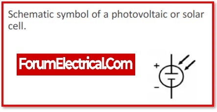
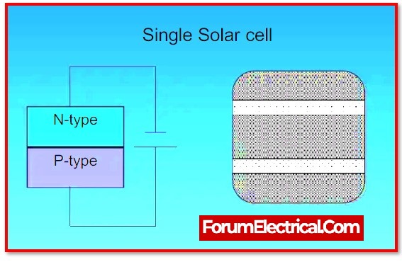
Symbolic Representation of Solar Cell
Solar cell can be symbolically represented by,
Construction of the solar cells
The following layers are used in the assembly of solar cells:
1). Solar cells and Silicon Layers
2). Strips of conductors and metal backings
3). Reflective-Reduced Layers
4). Frames and Glass
1). Solar cells and Silicon Layers
Solar cells, which are used to make solar panels, convert solar energy from sun into electricity, enabling them to produce power from UV illumination even on cloudy days.
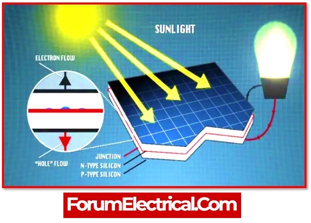
Between solar cell layers are semiconducting elements like silicon. Sunlight photons trigger the distinct electrical characteristics of each layer to create an electric field. The current required to produce electricity is produced by the photoelectric effect.
Although it has a slightly different design from standard p-n junction diodes, a solar cell is fundamentally a junction diode. On top of an almost thicker n-type semiconductor, a very small layer of p-type semiconductor is formed. And then add a few smaller electrodes to the p-type semiconductor layer’s top.
These electrodes don’t prevent light from passing through to the p-type layer. A p-n junction is located just underneath the p-type layer. A current-collecting electrode is furthermore provided at the base of the n-type layer.
2). Strips of conductors and metal backings
Each individual solar cell is made up of a few tiny rectangles or squares, joined by silver strips that direct all the power to a single location. On the top of those conductive metal strips, the solar cells have a metal backing.
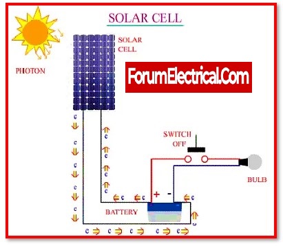
Solar panels of today are often constructed from 60 (or) 72 of these cells linked together. Afterward, the power leaves the solar panel and travels to other solar energy system parts like a battery (or) an inverter.
3). Reflective-Reduced Layers
Each solar cell has an anti-reflective coating applied to the top to improve the efficiency of the solar panel. Without it, more sunlight would be reflected away from the silicon rather of being absorbed in directly. Typically, this layer consists of silicon nitride (or) titanium oxide.
4). Frames and Glass
To guard against breakage and other environmental harm, a glass covering covers the solar cell array.
Furthermore, frames are used to attach the solar panels easily during installation, which lessens the labour intensiveness of installation & maintenance. They often are made of aluminium, and when they are joined with the other parts of the mounting system, they create a solid solar power array.
Working Principle of the Solar Cell
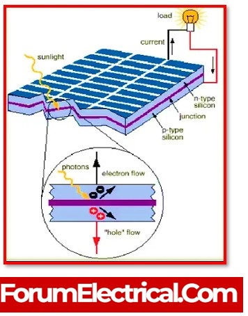
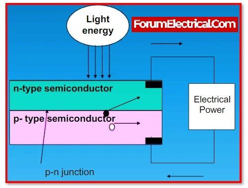
Light photons readily pass through the very thin p-type layer at the p-n junction when it comes into contact with it. The photons from the light source provide the junction enough energy to make many electron-hole pairs. The junction’s thermal equilibrium state is broken by the incoming light. The depletion region’s free electrons may move swiftly to the junction’s n-type side.
Similar to the depletion, the p-type junction side may be readily reached by the holes. The junction barrier potential prevents new generated free electrons from continuing to cross it once they reach the n-type side.
Similarly, when the newly formed holes approach the junction p-type side, they are receptive to the same barrier potential that defines the junction. The p-n junction will act like a miniature battery cell as junction one side, the n-type side, experiences greater electron concentrations and the other side, the p-type side, experiences higher hole concentrations. A voltage known as the photovoltage is turned up. By placing a smallest load across the connection, it may induce a small current.
VI Characteristics of the Solar Cell
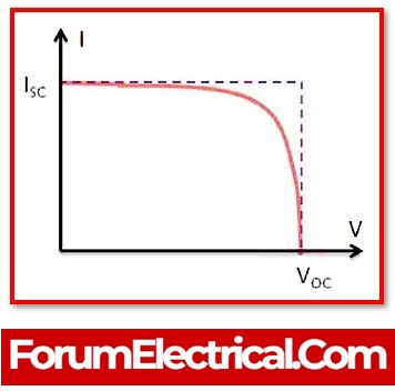
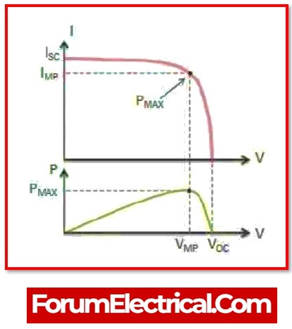
The V – I characteristics of a solar cell (or) the current-voltage (I-V) characteristics of the typical silicon PV cell working under normal conditions. A single solar cells or solar panel’s output current & voltage define how much electricity it can generate (V x I). The power curve above may be generated for a certain radiation intensity by multiplying all voltages, from the short circuit to the open circuit, point for point.
When the solar cell is open circuited and not connected to any load, the current will be zero & the voltage across the cell shall be maximum. This voltage is referred to as the open circuit voltage (VOC) of a solar cell. When the positive and negative leads are linked together, the voltage across the solar cell is zero, but the current exiting the cell is maximum, which is also referred to as the solar cell short circuit current (or) ISC.
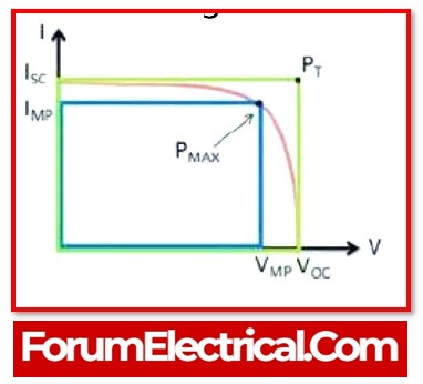
The power, on the other end, reaches its peak at Imp& Vmp for a certain current-voltage combination. To put it another way, the top right corner of the green rectangle symbolises the place where the cell generates the most electrical power. MPP is an abbreviation meaning “maximum power point.” As a result, the maximum power point is referred to as the ideal operating point of a solar cell (or panel).
Pmax=Vmp X Imp
is the maximum power which may be extracted from the device.
Pmax=IL X VOCX FF
is the max power that can be described in regard to VOC and IL.
High fill factor (FF), ISC, and VOC values are desired for an efficient cell.
When calculating the fill factor (FF) of a solar cell, the ratio of ImVm to IscVOC is utilised.
ImVm/IscVOC
Its value is between 0 and 1, respectively.
The maximum power point, also known as the MPP, of a solar cell may be found near the V-I characteristics curve bend. The proper values of Vmp and Imp may be calculated from the open circuit voltage & short circuit current as follows:
Vmp (0.8-0.90) VOC and Imp (0.85-0.95) Isc. Because the output voltage & current of solar cells are temperature-dependent, the actual output power will vary as the ambient temperature changes.
Parameters of a Solar Array
1).VOC stands for Voltage Open Circuit
This is the maximum voltage of the array when no load is connected to the terminals (an open circuit state).
2). ISC stands for Short Circuit Current
Maximum current of the PV array when the output connections are shorted simultaneously (short circuit). This value is significantly higher than Imp, which reflects the usual operational circuit current.
3). MPP stands for Maximum Power Point
The array power output that is linked to the load (batteries, inverters) achieves its maximum value when MPP = Imp x Vmp. The peak Watts (or) maximum power point, of a solar array are measured in Watts (W) (Wp).
4). % eff = Efficiency percentage
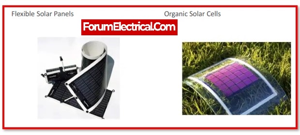
The efficiency of a photovoltaic array is defined as the ratio of the maximum electrical power that the array is capable of generating and the solar radiation that reaches the array. Depending on the kind of photovoltaic cell that is used (amorphous, polycrystalline, monocrystalline, or thin film), the efficiency of a conventional solar array is often rather low, ranging from roughly 10 to 12 %.
Materials in Solar Cells
The materials utilised for this reason must have a band gap of less than 1.5eV. Materials that are often utilised include:
- Silicon.
- CuInSe2 – Copper indium selenide
- CdTe – Cadmium telluride.
- GaAs – Gallium arsenide.
Material Selection Criteria for Solar Cells
- The band gap must be between 1eV and 1.8eV.
- It is required to possess a degree of optical absorption that is sufficiently significant.
- It must be electrically conductive.
- The raw material(solar material) must be abundant, and the material’s cost must be reasonable.
Advantages of the Solar Cells
- Because there are no moving components, it needs minimal maintenance.
- It is simple to extend the system as needed by adding solar arrays to the current system.
- During the production of solar electricity, solar cells produce no pollution or waste products.
- Solar cells have a lifespan of more than 15 years.
- Solar energy is provided free of charge by the cosmos.
- Its functioning needs less skilled workers.
- These are not harmed by extreme weather conditions; in fact, certain solar cell modules operate better in colder weather.
- The cost of generating electricity using solar cell devices continues to fall.
- Solar cells are extensively employed in a variety of applications such as air conditioning, lighting, water heating, watches,calculators, satellites, and so on.
Disadvantages of the Solar Cells
- High price.
- Not appropriate for all circumstances.
- Storage of power is a significant issue.
Applications of the Solar Cells
- Sets of water pumps for micro irrigation.
- At ports, used in ships navigation.
- Radio & television sets for communication.
- System for monitoring the weather.
- Signalling equipment for railways.
- Lightning on the street.
